|
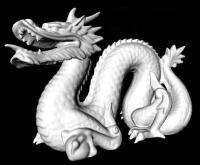
User's Manual for DRAGON Separator Hardware
Revision history
| Version |
Author |
Description |
Date |
| 1.0 |
D.A. Hutcheon |
Initial document |
3 January 2003 |
| 1.1 |
D.A. Hutcheon |
Details about FCM2 |
2 April 2003 |
| 1.2 |
D.A. Hutcheon |
ED DAC fix |
9 June 2003 |
| 1.3 |
D.A. Hutcheon |
FCM2/Beta-1 switch |
20 Nov 2003 |
| 1.4 |
D.A. Hutcheon |
FCM2/AUTO roughing |
20 Mar 2007 |
| 1.5 |
D.A. Hutcheon |
Beta Mon effcy note |
23 June 2008 |
| 2.0 | D.A.Hutcheon |
Decadal update | 20 March 2019 |
Contents
- Magnets
- Dipoles
- Quadrupoles
- Sextupoles
- Steerers
- Electrostatic dipoles
- Diagnostics
- Faraday cups
- FCF and the MCP
- FCM2
- Slits
- Beam centering monitors
- Beta monitor
- CCD camera
- Vacuum
- Pumping down a slit box volume
- Venting a slit box section to 1 atm
- The ED tanks
- Recovery after a power outage
- Safety fence
- Where is that controller?
The DRAGON magnets include 2 dipoles (MD1, MD2), 10 quadrupoles (Q1-Q10),
4 sextupoles (SX1-SX4) and 5 double steerers (SM0-SM4). Regulated DC
power supplies for the magnets are located on or under the (purple) DRAGON
platform. The power supplies are interlocked to thermal switches (all
magnets) and to flowmeters for cooling water (all except SM1 and SM2).
The flow of cooling water to each magnet is monitored by a meter connected
to
an "intelligent flow controller" box mounted at the east railing on the
upper platform. Table 1 gives the channel
assignments in the flowmeter controllers. Water flow and
thermal switches attached to the magnet coils are interlock inputs to the
magnet power supplies. If EPICS indicates no water flow, check first to
see if the rotor of the flowmeter (located at the magnet) is turning.
If the rotor is turning rapidly, go up to the flow controller, open the
front cover and look for a flashing light, indicating good flow, on the
channel in question. If the rotor is turning but the interlock condition
cannot be reset (yellow text changing to black) by the RST button ,
consult
Controls group. If the rotor is not turning, either the water has been
turned off or the flowmeter has stopped working: call Beamlines group or
consult with ISAC Operations.
Table 1: Channel assignments in DRAGON flow controllers.
| Unit |
Channel |
Magnet |
| Upper |
1 |
Q1 |
| 2 |
Q2 |
| 3 |
Q3 |
| 4 |
Q4 |
| 5 |
Q5 |
| 6 |
Q6 |
| 7 |
Q7 |
| 8 |
Q8 |
| Middle |
1 |
Q9 |
| 2 |
Q10 |
| 3 |
MD1 |
| 4 |
MD2 |
| 5 |
SM0 |
| 6 |
-- |
| 7 |
SM3 |
| Lower |
1 |
SM4 |
| 2 |
-- |
| 3 |
SX1 |
| 4 |
SX2 |
| 5 |
SX3 |
| 6 |
SX4 |
| 7 |
-- |
| 8 |
-- |
Designed to bend particles with maximum rigidity of 0.5 Tesla-m (150
MeV/c), the dipoles have a maximum rated current of 500 A.
(See G.S. Clark design notes TRI-DN-98-12 and -98-10.)
The magnet power supplies are designed to give a DC current stable to
0.01%. The MD1 power
supply is beneath the platform on the north side, and the MD2 supply to
the south. The AC breakers for the Philtek power supplies are located in
a panel under the platform at the foot of the stairway.
Control of the dipole power supplies is via interface cards on a Canbus
circuit. The EPICS page for MD1 (or MD2) is called from DRAGON
menu OPTICS | Optics(1) ( Optics(3) for MD2) and clicking on the MD
icon. The page has buttons to turn the magnet On ("1") or Off ("0") and
to reset latched interlocks ("RST"). If the magnet refuses to turn On
remotely, try going to EPICS page Diagnostics | Canbus
diagnostics | DRA:MD1 and hit "RST P/S".
A Setpoint slider and current readback are calibrated in Amperes.
The MD magnetic field is sensed by an NMR probe (#3 probe for MD1 and
#4 probe for MD2) inserted through a hole in the "inside" return yoke
at beam height. A jig holds the probe at a well-defined position and
orientation, just outside the vacuum vessel, in a region where the field
is still flat. Each probe is connected to a CERN-type controller located
in the electronics rack under the platform. Controller output (field in
Gauss) is displayed on a front-panel display and is sent also to EPICS
where it is presented as part of the MD1 (or MD2) panel. The controller
can search and lock on the resonance - when it locks, the field value
displayed by EPICS changes from white to blue. The (rather narrow) search
range is set by a 0-6.5V level fed in the back of the controller unit.
The level comes from a supply which is controlled by slider/On/Off/status
buttons on the bottom row of the MD1 entry of Optics(1) (Optics(3) for
MD2).
The search range is not quite a linear function of input voltage (slightly
S-shaped): if the NMR is not locked, observe the search range of the
displayed (white) field values and adjust the voltage to make the search
range bracket the expected field. (The expected value for MD1 can be
calculated from the Setpoint current: B = 11.7*I + 100. For MD2:
B = 16.5*I.)
Quadrupoles 1-8 were built to TRIUMF design by Sunrise Engineering
(Delta). Two (Q1, Q6) are `"4-inch" quads (see G.M. Stinson
design note TRI-DNA-98-4); five (Q3,Q4,Q5,Q7,Q8) are "6-inch" quads (see
G.M. Stinson, TRI-DNA-98-5); one (Q2) is "6-inch" with a 6% sextupole
component (G.M. Stinson, TRI-DNA-99-3). The 4-inch quads were designed to
produce a field gradient of 0.5 kG/cm at maximum current 325 A, the 6-inch
quads 0.36 kG/cm at 325 A.
Quads Q9 and Q10 (CERN "Smit-Elma") have a 15-cm aperture (see
G.S. Clark design note TRI-DN-98-17). Pole tip fields were surveyed to
be 19 Gauss/Amp.
The quadrupole power supplies, designed for 0.1% current stability, are
rack-mounted units (Xantrex and Power Ten)
located on the power-supply platform.
Their AC breakers are in panel P456 at the east railing of the platform.
Quadrupole fields are measured by Hall probes, jig-mounted in the middle
(longitudinally) of each quad. The probes for Q1-Q8 are located in the
gap between poles, at the radius where the field is a maximum. On Q9 and
Q10 this location was not accessible. The Hall probe control boxes,
located close to the quads, are on a Canbus daisy-chain. When viewing
quadrupole field values on the EPICS Optics pages, make certain that the
page is wide enough so that the high-order digits are displayed.
Expected B/I readings for Q1 and Q6 are 11.6 Gauss/Amp; for Q3,4,5,7,8 it
is 12.5 Gauss/Amp; for Q2, 12.9 Gauss/Amp; for Q9 and Q10,
nnn Gauss/Amp.
SX1 and SX2, 6-inch sextupoles originally installed in meson channel M13,
were surveyed to have pole-tip fields 18.5 Gauss/Amp. SX3 and SX4 came
from channel M15; they give 18.1 Gauss/Amp.
The sextupole power supplies are rack-mounted units (Xantrex)
located on the power-supply platform.
Their AC breakers are in panel P456 at the east railing of the platform.
They are not equipped with Hall probes.
The double-steerers can deflect ions of maximum rigidity (0.5 T-m) by up
to 25 mrad in x and/or y. Steering magnets SM1 and SM2, obtained from
Chalk River, are air-cooled and have maximum rated current of 5 A.
(If they are to be used above 3 A, a fan or other forced-air cooling
should be installed.) SM3 and SM4 are water-cooled, with maximum current
100 A and have 6-inch apertures (see G.M. Stinson design note
TRI-DNA-99-1); they have 3.88 Gauss/Amp. SM0 (a.k.a. "the Wobbler") is
used for separator optics studies, for which it is mounted at the target
position. It is a 4-inch design (G.M. Stinson, TRI-DNA-98-7), water
cooled, maximum current 100 A, having 3.24 Gauss/Amp.
The steerer power supplies are rack-mounted units (Xantrex and zzz)
located on the power-supply platform.
Their AC breakers are in panel P456 at the east railing of the platform.
When SM0 is not in use (most of the time), its power supply will be locked
out; thus, most of the time the EPICS icons for SM0X and SM0Y are red.
Dipoles ED1 and ED2 consist of polished cylindrical titanium electrodes
having a gap
of 100 mm and radii of curvature 2 m for ED1, 2.5 m for ED2. Design
bending power is 8 MV (energy/charge 4 MeV/q) which requires electrode
voltages of ±200 kV on ED1, ±160 kV on ED2. They are housed in
large cylindrical tanks. The HV units are stacks powered by Glassman
r.f. supplies; the stacks are immersed in SF6 gas at 2 atm, enclosed in
re-entrant ceramic insulating cylinders.
The tank is encased in 6 mm of lead, to absorb x-rays given off during
voltage conditioning. X-ray production is monitored by thick plastic
scintillators connected to photo-multiplier tubes, mounted above a viewing
port on the lid of each vacuum tank. The PMT high-voltage supply is a
LeCroy unit, manually controlled, in the 19'' rack below the platform.
Customary HV setting is -2000 V. A discriminator in the same rack
provides logic signals which are made available to the EPICS control system.
The Glassman supplies are close to their respective electrodes, in a
19'' rack for the anodes and slung from the vacuum tank for the
cathodes. They are controlled via a Canbus link. The AC to the Glassman
supplies is interlocked: cages around the feed-throughs to the stacks must
both be closed; there must be less than 0.5 atm in the tank as measured by
a mechanical gauge; there must be less than 10-5 Torr in the tank as
measured by an ion gauge; at least one of the tank pumps (turbo, cryo or
ion) must be on. The interlock boxes are located in the racks that hold
the anode power supplies.
The EPICS display shows set voltage and stack current for anode and
cathode. Normally the current reading is about 1 µA per 6 kV.
Following a power glitch or a re-boot of EPICS it is not uncommon for
the HV to refuse to come on. If it is not due to a genuine interlock
fault, go to the EPICS ED page and bring up the Expert panel. Change the
"I+" setpoint to 0 then to 40, and do the same for the "I-" setpoint.
("40" is the current limit in µA.)
If HV still doesn't come on, call a high-voltage expert.
A spark in an ED or some other electromagnetic pulse may cause the DAC
which sets electrode current limit to lose its calibration. A symptom of
this is that when the HV is turned On, the voltage and current will
momentarily ramp up but almost immediately go back down to near zero.
A way to check for this problem is to use the "loopback" test of the
CANBUS system: from the DRAGON EPICS menu select Diagnostics|Canbus
and then the ED in question. For the problem electrode (+ or -) change
the I button from "no LB" to put it in loopback mode, whereby the DAC
output is fed directly back into the ADC. Run the appropriate slider bar
up and down and you should normally see the Readback and Setpoint values
move up and down together. If they do so, you have a different problem
and should call an HV Expert. If they do not have the same value, try to
recalibrate the DAC: momentarily unplug the CANBUS daisy chain input to
the controller box in question (ask an ISAC Operater for help with this).
If this doesn't fix the problem, call an HV Expert.
NOTE: unplugging the CANBUS will cause all CANBUS-controlled devices
(magnets, ED) to forget their settings and they must be turned on again
and set to proper values.
The electrodes must be "conditioned" for stable operation at high
voltage. As the voltage is increased, at some point the current will jump
up to the current limit of the supply, vacuum will get worse by an order
of magnitude, and the x-ray counts will jump from from tens or hundreds
per second to many tens of thousands per second. If the voltage is set
just above the onset of these effects, the system should return to good
vacuum, low x-ray counts and 1 µA per kV within a minute or so.
Then the voltage can be raised slightly and the cycle repeated. For
detailed instructions on HV conditioning, consult the
EPICS routine for conditioning ED1, ED2 at high voltage.
Note: If signs of conditioning persist for more than approx. 1 minute after a
small increase in voltage (say 10 V), this may indicate a problem such as
carbon tracking along the ceramic insulator or within the HV stack;
reduce the voltage and consult an HV expert.
DRAGON has 4 controllable Faraday cups: FC1 is between Q2 and MD1; FCCH is
after the
slits at the Charge Selection focus following MD1; FCM is after the slits
at the Mass Selection focus following ED1; FCF is after the Final slits at
the end of the separator. They can be inserted or retracted by a
pneumatic actuator, controlled via EPICS. The EPICS control panel for
each cup allows selection of a full-scale current range for the current
integration. The readout noise is approximately 10 pA, setting a lower
limit on the beam currents which can be read reliably.
An integration time of 1-2 seconds has been built into the ADC readout
routine, so several seconds are needed for the readings to reach a stable
value.
Each Faraday cup is equipped with a bias ring at the front, to suppress
the escape of secondary electrons. If the "good bias" indicator is not
green, click on "Bias" and set the bias to greater than 100 V on Reverse
polarity.
The bias power supplies and the charge-integrating ADCs are located in a
Controls VME crate in rack 23A on the platform.
A fixed-position Faraday cup FCM2 has been mounted in the
Mass Slit Box, downstream of the slits and 12 cm to the "low
mass" side of the standard cup FCM. (See the location
of the cup.) The 12-cm offset should catch
beam of the selected charge state when ED1 is tuned for recoils
having 4/3 the mass of the beam. The exact value of the mass ratio
must be determined by finding the value of ED1 which centres the
beam in FCM2 -- if 12 cm offset is not close enough to the 4/3 mass
ratio, there is provision for adjusting the offset (manually).
Two pairs of motor-driven slits are located at each of 3 focus
points: XSLITC and YSLITC are the horizontally-moving and
vertically-moving slit pair at the Charge selection focus; XSLITM and
YSLITM are at the Mass selection focus; XSLITF and YSLITF are at the Final
focus.
Each member of a pair (e.g. the Left and Right parts of an XSLIT pair) is
driven by a stepping motor. However, the user specifies the Width and
Position of the slit opening and EPICS control takes care of computing the
Left and Right (or Top and Bottom) positions. The sign convention is that
of GIOS or TRANSPORT ion optics codes: positive x is to the left, looking
downstream in the direction of particle motion; positive y is up.
The stepping motor controllers are located in rack 23A on the platform,
below the VME crate. Calibration of slit positions is done by means of a
microswitch at the "Out" position of each drive. Following a power
failure or an EPICS re-boot, it is necessary to do a
"Calibrate" operation for each slit drive. This causes the slit member
to be driven out to the outer (microswitch) limit, then in to the position
required by the Position and Width settings.
A 3rd microswitch protects against an attempt to close the slit pair
beyond the point of contact ("negative Widths"). This means that care
must be taken if very small Widths are called for: a Calibrate operation
may never complete when Width=0 if the collision microswitch engages
before the motor has stepped to the computed 0 width; a change in Position
when Width is < 2mm may produce the "collision" condition during the
movement of the slit members. In the latter case, the EPICS driver will
stop the "pursuing" member but allow the "leader" to continue to its
proper destination - the indication that this has happened is that
the read-back position (blue number) doesn't end up at the Setpoint
number for Width and Position and the "Closed limit" light is green for
the "leader".
The true position of XSLITC, the slits defining horizontal position
at the Charge Slit Box, is a key datum for calculation of beam energy.
In addition to counting step commands given to the stepping motors,
SXLITC has position readout by a Mitutoyo linear slide, whose values
appear in the EPICS page DRA:XSLITC as "linear scales". (There is a
0.3 mm offset between this scale and the true zero as determined
by sighting through MD1.)
In case there is concern that the slit drive has not stepped to the
desired position, the X slit pairs are equipped with pointers and
millimeter scales to allow independent verification of the actuator
position. The scales are marked also with the readings that correspond to
the out-limit microswitches; these numbers should appear in the EPICS
table used in Calibration.
As for the Faraday cups, slit currents are sent to an ADC. The slits have
no bias for secondary electron suppression.
Six beam centring monitors (BCMs), together with the 3 sets of slits and
the target aperture, allow beam position to be defined at two locations in
each of the 5 straight-line segments of the separator. Each BCM consists
of 4 plates arranged in a 2x2 array, mounted on insulators and separated
from each other by a small gap. The current from each plate is read by an
ADC and EPICS combines the 4 readings to show total current plus asymmetry
of current in each of left-right and top-bottom directions.
Insertion and retraction is by pneumatic actuator. If the device fails to
reach its In limit (defined by a microswitch) in time (e.g. low compressed
air pressure), a Timeout is indicated. Timeout flag may be cleared with
the RST button.
The current range scale must be chosen so that none of the quadrants is
shown with full-scale current, or else the asymmetry calculations will not
be valid. There have been occasional problems with a quadrant of a BCM
reading a substantial current, even with no beam on it. This may be due
to a flexible lead shorting out, for example, which requires venting a
section of the separator in order to investigate further. A temporary
work-around is to steer the beam so that none of it falls on the
"bad" quadrant and adjust the horizontal or vertical steering for equal
currents on each of the two pairs of adjacent plates, in turn.
The Beta monitor is a pair of plastic scintillators which detect beta
particles emitted by radioactive beam atoms which stop in the Mass slit.
Located in air in a well in the Mass focus diagnostics box, the Beta
monitor subtends about 1/1500 of 4 pi solid angle at XSLITM. The rate
for coincidence detection of a particle in the two scintillators is
presented to the EPICS virtual scaler and the MIDAS DAQ.
The coincidence response depends upon the energy distribution of the decay
betas: a detected beta must have eneough energy to pass through the
entrance window, through the first scintillator (6mm) and far enough into
the second scintillator to be above discriminator threshold.
As well as the coincidence rate, the front-counter singles rate is sent to
the MIDAS scaler.
Connection is by a coax cable as indicated by the blue line:
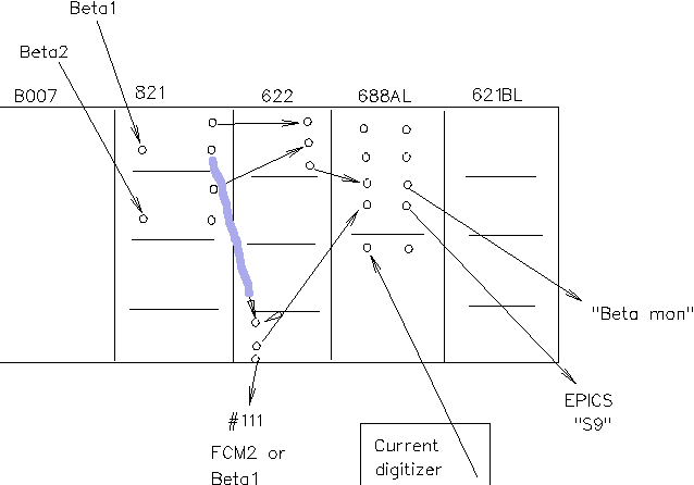
The HV for the plastic scintillator photo-multiplier tubes is from
channels 2 and 3 of the same LeCroy HV unit which supplies the ED x-ray
monitors. The discriminators, coincidence unit, and level adapter modules
are in the same NIM bin as the NMR controllers (rack under the platform).
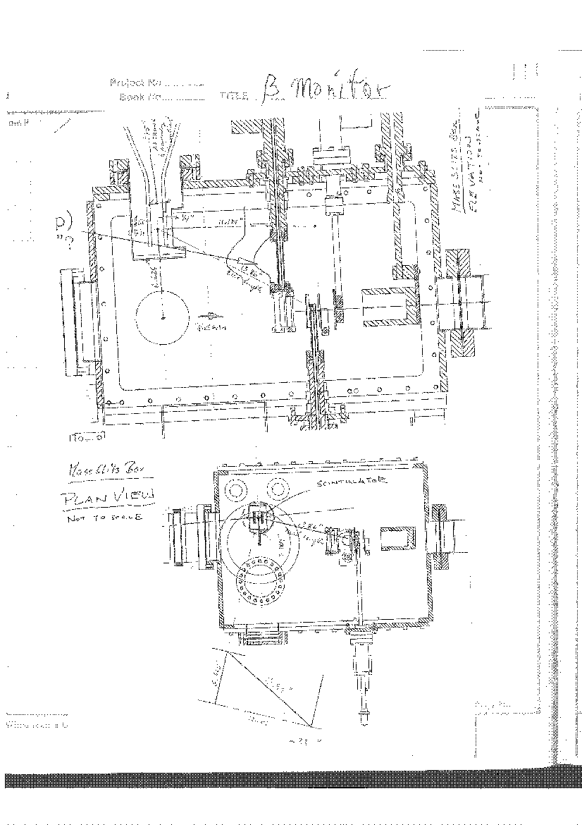
Drawings and notes on expected efficiency for detection of betas from decay of
Na-21 beam from DAH logbook:
 A CCD (Starlight Xpress MX7-C) views
upstream through an alignment port of dipole MD1, to the target position.
When beam is passing through a gas target, it emits light which can be
imaged on the CCD. The position of the beam can be determined relative to
the apertures of the gas cell with sub-millimeter accuracy. The width of
the beamspot can be seen also (but it is a measure of beam width only if
the light comes from beam ions, not target gas which may have diffused
before recombination).
A CCD (Starlight Xpress MX7-C) views
upstream through an alignment port of dipole MD1, to the target position.
When beam is passing through a gas target, it emits light which can be
imaged on the CCD. The position of the beam can be determined relative to
the apertures of the gas cell with sub-millimeter accuracy. The width of
the beamspot can be seen also (but it is a measure of beam width only if
the light comes from beam ions, not target gas which may have diffused
before recombination).
The MX7-C is controlled from a dedicated PC via the Starlight Xpress
driver. 2-d density plots may be made (generally need to start with a
Linear Stretch of the intensity scale in order to see the beamspot).
A Photometry option gives counts for individual pixels. The counts from
the entire pixel array may be stored in a .FITS file for later analysis.
The location of the gas cell aperture may be determined by closing
isolation valve HEBT2:IV8 and turning on ion gauge IGU3 (and opening valve
IV11!). The outline of the 6mm cell entrance aperture appears backlit
by light scattered off IV8.
The separator vacuum system has 5 sections, each with independent
high-vacuum pumps, which are connected in a common system when ions pass
through. These sections are: the ED1 tank; the ED2 tank; the Charge slit
box, MD1 vacuum box and pipe between the Charge box and ED1 tank; the Mass
slit box, MD2 box and other pipe between ED1 and ED2 tanks; the Final slit
box and pipe between it and ED2.
A single roughing pump connects to one (at a time) of these volumes. It
is a Leybold Dri-pump - oil-free, pumping down to about 50 mTorr.
Similarly, all the turbo pump backing is done by a second Dri-pump.
Interlock conditions on opening roughing valves (RV) or backing valves
(BV) protect against gross Operator errors, such as trying to rough down a
volume when its vent valve is open. (However, this is true only if the
interlocks have not been Bypassed - if a valve has "Interlocks
bypassed" and you don't know why, find out why before opening it.)
Turbo pumps have a Full speed (38k rpm) and a Low speed (25k rpm)
mode. If, for example, a turbo pump is being run simply to maintain good
vacuum in a slit box for a few days, it may be desirable to run it at Low
speed to limit wear and tear. The EPICS control panel for each turbo pump
has a toggle switch to change between Full and Low speed modes. An indicator
light ("Low Speed") on the EPICS panel is yellow if Low speed is selected,
black if Full speed is selected. If Full speed is selected while the
turbo pump is at Low, EPICS may turn the pump Off. If this happens, it
will be necessary to have the Backing pump on and connected (see note
below regarding AUTO mode) in order to restart the turbo pump. Note also
that with no gas load a turbo pump will take a long time to spin down from
Full to Low rpm. The "At speed" EPICS light is green only if the speed is
above a defined threshold (usually 36k rpm), whatever the selected speed;
to know the actual turbo speed it is necessary to go to the turbo
controller box and examine its visual display.
After a finite number of hours of running, the
Dri-pumps will have to
undergo an expensive maintenance. To limit the number of Roughing pump
hours, it should not be left running when not needed. The
running time of the Backing pump can be limited by selecting the AUTO
feature, using the "Pumping mode" toggle switch at the right-hand side of
the main menu for EPICS control of DRAGON. Connected to the common
backing line is a storage tank. In AUTO mode the Backing pump (BP31)
remains off and isolated from the backing line, until the pressure in the
backing line and tank reaches about 300mT. At that pressure BP31 turns
on, valve PV31 opens and the pump runs for 5 minutes before PV31 closes
and BP31 shuts off. Normally, BP31 should come on only once or twice per
day when in AUTO mode.
When more than one section of the separator is to be pumped down, it is
advisable to switch from AUTO to MANUAL pumping mode. The reason may be
found in the Device Note for PV31: "When in automode this device is forced
off for 15 minutes after CG31A reaches less than 80 mtorr". The backing
pump has the hidden condition "In auto mode this device is forced off as
long as PV31 is forced off: see PV31 note." Attempting to pump down two
sections of the vacuum may have the unexpected effect that in AUTO mode
BP31 can be turned on "by hand" for the first section but not for the
second section.
The following describes the steps in pumping down the Charge slit box
volume, but it applies to the Mass slit box or Final slit box with
suitable change in label of valves, pumps or gauges.
- Close vent valve VV21.
- Turn on roughing pump RP21 and when convention gauge CG21B goes
below 100 mTorr, open pump valve PV21.
- Open RV21 and observe box pressure on CG21. Pressure should
decrease steadily until CG21 reaches 100 mTorr, when RV21 will close.
- If backing pump BP31 is not already running and PV31 open, turn on
BP31 and open PV31.
- Open BV21 and turn on turbo pump TP21 (it may be necessary to RST
latched interlock conditions). TP21 icon should turn dark green and
CG21 drop to a near-zero reading. After 10-15 minutes the turbo should
get up to speed and its icon change from dark green to light green.
- Turn on ion gauge IG21. If the volume has been at atmosphere,
initial IG21 readings may be in the 10-5 Torr range and will only
slowly (over hours) decrease to 1-2 × 10⁻⁶ Torr as water is
desorbed from inside surfaces.
The Final slit box has the complication that it may contain fragile MCP
target foils. Roughing down begins through RV54, which is in series with
a manual throttle valve that has been adjusted to limit initial pumpdown
to a foil-friendly rate. If it is known for certain that no foils are
mounted (e.g. by looking in the window of the MCP Foil mounting plate),
fast pumpdown may be done through RV52 (with Bypassed interelocks).
The Final slit box is followed either by a small vacuum box containing a
Si strip detector or by a gas-filled ionization chamber. In the first
case the "ED2 to SSD" option should be selected under the Vacuum menu.
For the ionization chamber choose "ED2 to IC". Operation of the
ionization chamber is complicated and its use of the vacuum system is
detailed in the section describing general operation of the IC.
This procedure for the Charge slit box applies also to the Mass and Final
slit boxes, with suitable change of labels on gauges, pumps and valves.
- Close isolation valves IV11 and IV21.
- Turn off ion gauge IG21 and turbo TP21, and close backing valve BV21
\item toggle vent valve VV21 open and closed as quickly as possible, to
start the turbo braking process. CG21C may climb to approx. 10 Torr, and
then gradually decrease as TP21 spins down. When CG21C reaches 1-2 Torr,
allow another quick gulp through VV21.
- When CG21C and CG21 become nearly equal, start the main venting:
at the compressed Nitrogen cylinder beside MD2, verify that the manual
valve "LN2 dewar pressure" is closed and "Separator vent" is
open. Set the "dead-man switch" timer to 15 minutes. (In case you get
distracted midway through the venting process, this prevents venting the
whole cylinder of nitrogen by mistake.)
Locate the vent line pressure relief valve (downstream of MD2, knee
height, by valve VV21A. Adjust the pressure regulator (clockwise
increases pressure!) until gas can be felt escaping the pressure relief
valve.
- Open VV21 and watch pressure rise on CG21. When it reaches 760
Torr, valve off the nitrogen cylinder.
Only rarely will the ED tanks be vented to atmosphere. The general user
is strongly discouraged from doing this, because of the lengthy time it
takes to recover high vacuum (10-7 Torr level) after a venting.
More likely will be a requirement to resume pumping if all the pumps
are off following a power outage. Each tank is equipped with:
- A turbo pump (Varian 1000 l/s) used to pump down from
"intermediate" vacuum (too high for the ion gauge, too low for a
convection gauge) to the 10-6 Torr range. Otherwise, usually turned
off and valved off to reduce wear \& tear.
- A cryo pump used for its high pumping speed, during DRAGON operation
with beam. A single compressor runs 2 cold-heads, one at each ED tank.
It is located near the Mass slit box, next to the Roughing and Backing
pumps.
- An ion pump used to maintain vacuum when DRAGON is not in use for
extended periods. It must be turned on or off manually - only the
pressure readout is sent to EPICS, to indicate when the ion pump is on.
At least one of the 3 pumps must be on in order to turn on the tank ion
gauge and (because they are interlocked to the IG) the electrode high
voltage supplies.
The interlocks on
the roughing valves (RV33, RV53) are such that they allow
only the pump-out of a warm (> 250 K) head, and the cryos (CP33,
CP53) can be turned on only if they have been pumped down below 150 mTorr.
If a power outage occurs during a run, it may be necessary to pump on the
cryo head(s) if they have warmed up enough to release the gunk that they
have pumped out of the tank.
- If the outage was brief and the pressure in
both CG33C and CG53C is below 100 mTorr, restart the cryos CP33 and CP53.
The temperatures of the CPs and the pressure at the associated CGs should
drop. There should be a "rrr ... rrr ... rrr ..." sound from the
cold-heads at the ED tanks; if there isn't, try turning the power off and
on at the compressor (inside the fence, by the roughing and backing pumps)
and re-starting CP33, CP53. If this doesn't work, consult an expert.
- If the outage was long enough that CG33C or CG53C pressure rose
above 100 mTorr but the temperature at CP33 or CP53 stayed well below
250K, it will be necessary to pump away some of the gas that was released
by the warm-up of the cryo.
- On the DRAGON EPICS menu go to Bypass/force | Bypass vacuum and
click On RV33 (or RV53). The text should change from black to yellow,
indicating the interlock has been bypassed.
- Turn on RV21 and open PV21. When CG21A < CG33C (or < CG53C),
open RV33 (or RV53).
- If the pressure at CG33C (or CG53C) drops very slowly and rises
rapidly when the RV is closed, a lot of gunk has been released and
pumpdown may take a considerable time. If the tank turbo pump TP31 (or
TP51) is not already running, turn it on (following the instructions as
given above for TP21 in the Charge slit box volume). When TP31 (or
TP51) gets up to speed and provided CG31 (or CG51) is < 100 mTorr, open
gate valve GV31 (or GV51). It should then be possible to turn on the tank
ion gauge and HV, if time is of the essence and you want to resume use of
the separator.
- Continue pumping on the cryo-pump until pressure drops to 100 mTorr
and when RV33 (or RV53) is closed the pressure rise is slow enough that
CP33 (or CP53) can be turned on before pressure goes above the 150 mTorr
interlock limit.
The temperatures of the CPs and the pressure at the associated CGs should
drop. There should be a "rrr ... rrr ... rrr ..." sound from the
cold-heads at the ED tanks; if there isn't, try turning the power off and
on at the compressor (inside the fence, by the roughing and backing pumps)
and re-starting CP33, CP53. If this doesn't work, consult an expert.
- Go to the interlock Bypass page and turn Off the bypasses on RV33
and RV53 (yellow text should turn to black).
- After pumping gunk from a cryopump, it often is seen that the
roughing pump RP21 can pump down only to approx. 150 mTorr instead of the
usual approx. 50 mTorr. (This may be due to release of large amounts of
water from the cryos.) Purge the roughing line and roughing pump:
close PV21 and vent the roughing line to nitrogen via VV21A (following the
instructions given above for venting a slit box volume); close VV21A and
pump out the roughing line through RV21. If this improves the vacuum at
CG21B, a second purge may be useful. If purging did not reduce the
pressure at CG21B, consult an expert.
Significant levels of radiation may be present when positron-emitting
radio-active beam is in use. Approximately 60% of the beam stops at or
near the Charge slits following MD1 and 40% on the Mass slits. Lead
shielding around the Charge and Mass slit boxes reduces the radiation to
acceptable levels at 1 m from the ion-optical axis of the separator.
A gated mesh fence prevents people from getting closer than 1 m to the
separator when radio-active beam is (or might be) delivered.
A number of gates allow access during maintenance periods or when stable
beam is being delivered from OLIS. Each gate has a lock and key. The key
can be removed only when the gate is locked; the key must be taken from
the gate and inserted in a "transfer panel" in order to release a key
which in turn is needed to get authorization for radio-active beam
delivery. The transfer panel is located on a post to the north of the
DRAGON end detectors.
The controller/power supplies for turbo pumps, ion gauges, motors,
etc. are mostly in 19-inch racks "near" the pump, gauge or motor being
controlled. The important racks are:
- Rack 7A - under the platform
- MD1, MD2 NMR
- HV4032A supply: XRAY1, XRAY2, BETA1, BETA2 PMT's
- IG32 (south end)
- TP32 (south end)
- Rack 18A - East of ED1 tank
- ED1 HV interlock box
- ED1 Anode HV supply
- IG21, IG31
- TP21, TP31
- ED1 ion pump
- Rack 26A - Southwest of ED2 tank
- ED2 HV interlock box
- ED2 Anode HV supply
- IG51, IG52
- TP51, TP52
- ED2 ion pump
- Rack 23A - on platform, North side
- EPICS VME crate
- Stepping motor drivers
- Rack 23C - on platform, North side
- Power supplies for SX1, SX2, SM1X, SM1Y, SM2X, SM2Y
- MD1, MD2 NMR ref. voltage DACs
- Rack 23D - on platform, North side
- Power supplies for Q1, Q2, Q3, Q4, Q5, SM0X, SM0Y
- Rack 24A - on platform, South side
- Power supplies for Q6, Q7, Q8, SM3X, SM3Y, SM4X, SM4Y
- Rack 24B - on platform, South side
- Power supplies for SX3, SX4, Q9, Q10
|