|
High voltage conditioning of the DRAGON electrostatic dipoles may be
achieved using the EPICS routine "Condition DRA:ED1/2." The conditioning
routine monitors properties of the dipole effected by the conditioning
(the tank pressure, the x-ray rate, the anode current, and the cathode
currents), and allows for a slow conditioning of the EDs under computer
control. To find out why conditioning may be necessary, please consult the
Separator Hardware User's Manual.
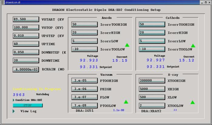
The routine may be initialized from the EPICS page "Optics|Condition ED1",
accessible from the DRAGON menu bar. This page allows for initialization,
monitoring, and termination of the HV conditioning.
HV Conditioning Algorithm
Each of the four monitored parameters (anode current, cathode current,
pressure, and x-rays) must be between 2 numbers ("Too Low" and "Low")
before a voltage increase will take place. Such an upward step in
voltage (an increase of "Upstep" kV) will only be considered by the
control loop once every "Uptime" seconds.
The need to step voltage back down because of increased activity in
any of the four monitored parameters is considered once every "Downtime"
seconds. The HV setpoint will be reduced by "Downstep" kV if any of
the four parameters lies in the range between "High" and "Too High".
Parameters lying between "Low" and "High" are neither a cause for a
down-step nor license for an up-step in HV. Instead, the control loop
will sit at the same voltage setpoint until another "Uptime" or "Downtime"
seconds have elapsed.
If any parameter is found to be higher than "Too High", the routine
exits from the control loop on the assumption that something has gone
wrong with a readback, or some other unexpected hardware failure has
happened. Similarly, the control loop will terminate if any parameter
is found to be "Too Low."
Conditioning can also be terminated if the user clicks the Stop
button on the conditioning page, or if some other agent (user or Scaling
routine) changes the Setpoint value from the value last set by the
HV Conditioner.
To set up HV Conditioner:
- Manually determine the HV Setpoint at which signs of conditioning appear
and enter this number as VSTART (in kV). [Consult figure below]
- Enter the voltage at which conditioning should end as VSTOP (in kV).
- Enter the step size for voltage increases as UPSTEP (in kV).
Suggested: 0.01
- Enter the minimum interval between steps up as UPTIME (in seconds).
Suggested: 120
- Enter step size and interval for voltage decreases as DOWNSTEP and
DOWNTIME, respectively. Suggested: 0.05 kV and 30 sec
- Specify the effective resistance of the HV stack (MOhms = V/uA) as
RCHAIN. (We are interested in the net current after stack current is
subtracted.) Suggested: 6000
- Specify the TOOLOW, LOW, HIGH, and TOOHIGH limits of anode current and
cathode current (uAmps). Suggested: -10, 5, 20, 50
- Specify the limits on pressure (in Torr).
Suggested: 0.7E-9, 5.0E-7, 3.0E-6, 3.0E-5
- Specify the x-ray rates. Suggested:
- ED1: 2, 300, 5000, 300000
- ED2: 2, 3000, 10000, 300000

Figure 1: HV conditioning EPICS page
Start the conditioning by clicking on the "Condition DRA:ED1" (or :ED2) button
at the bottom left corner of the page.
A watchdog timer should start counting up from 0 and keep counting as long
as the control loop has not been terminated. The read-back voltages and
currents as well as the most recent setpoint voltage are displayed in the
Anode and Cathode boxes.
In each of the four boxes a green triangle will
point up if everything is OK to step up the HV, or will point down if the
HV should be stepped down. If the control loop is terminated because
one parameter remained out-of-range, a red "stop sign" is displayed for
that parameter. The value which caused abnormal termination should appear
in the last part of the log file, which can be displayed by clicking on the
"View log" button at the bottom left corner of the page.
Dave Hutcheon
26 Feb 2003
|


