|
Use of the TUDRAGON
Gas Target
Revision history
| Version |
Author |
Description |
Date |
| 1.0 |
D.A. Hutcheon |
Initial document |
21 March 2007 |
Introduction
The TUDRAGON ("TUDA+DRAGON") target chamber replaces the standard target
chamber used for gamma-ray capture experiments at DRAGON. It is used for
reaction experiments in which charged reaction products are detected by
solid state counters inside the target gas. To accomodate these
detectors, the inner gas cell is longer and wider than the cell used in
gamma capture experiments.
The TUDRAGON chamber is windowless and uses the DRAGON gas recirculation
system.
New users should read "Operate the DRAGON gas target" which gives
operating instructions and safety information for the recirculation
system.
Description of the chamber
The TUDRAGON system consists of
- an inner gas cell containing the detector arrays and the target gas at
several Torr pressure. Beam enters and exits through differential pumping
tubes.
- a lid to which the inner cell and the detectors are bolted. It has
feed-throughs for the detector signals, as well as a gas inlet and
pressure transducer connection.
- an outer vacuum box. It connects upstream and downstream to
differential pumping stations and downward to Roots blowers in a
"plug-for-plug" replacement of the standard gas cell. The top lid
completes the vacuum enclosure.
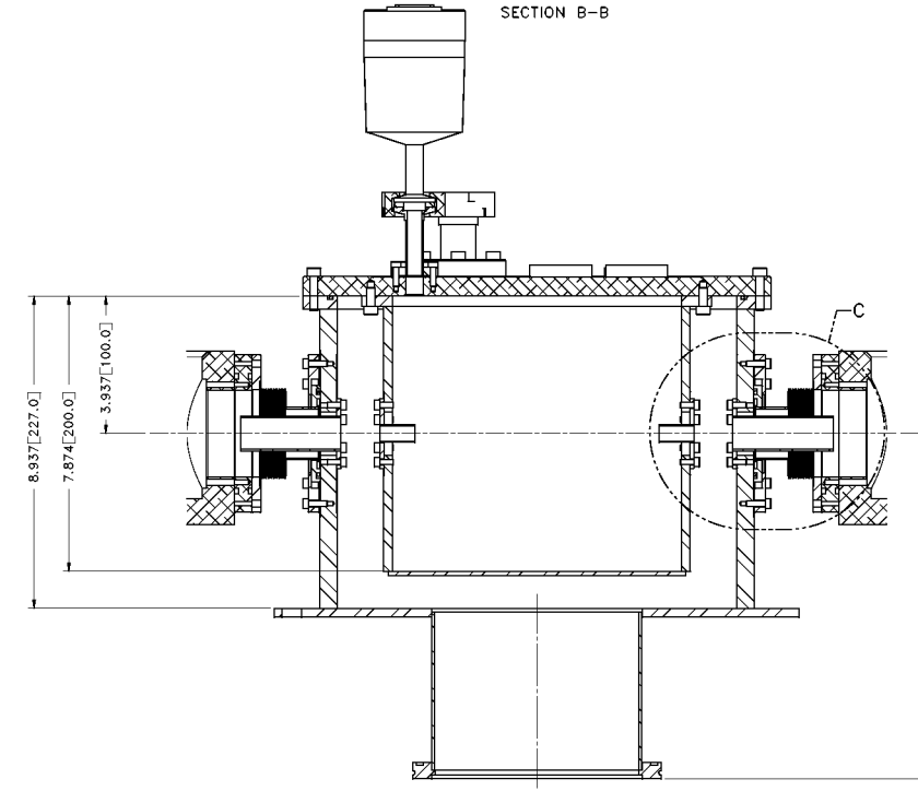
The TUDRAGON gas target chamber, part of drawing IEH0621D. Charged
particle detectors (not shown) are mounted from the lid, in the inner gas
cell.
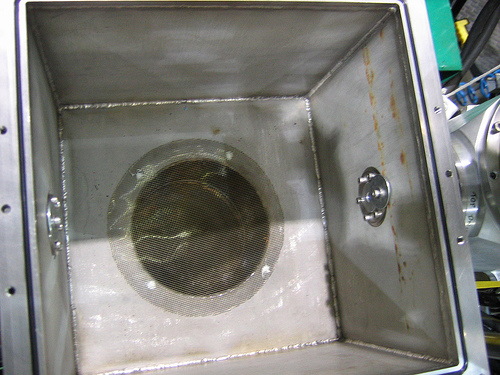
Below, a view of the inside of the outer vacuum box, showing a screen over
the tube
leading to Roots blowers. Also visible is the flange for the pumping tube
between this box and the first differential-pumping stage.
The inner cell used in radiative capture experiments has beam entrance and
exit apertures slanted at 30 degrees, to direct the jets of escaping gas
away from the tubes leading to the next stage of differential pumping.
The TUDRAGON cell had to be longer, forcing a shorter gap between it and
the outer vacuum vessel; pumping tubes inside the cell have been added, to
limit the gas load on the recirculation pumps. Consequently, the gas
pressure profile is expected to decrease from the central pressure
within 1-2 tube diameters of the inside end of the tubes.
Tests with no detectors in the gas cell showed that to reach hydrogen
pressures as high as 10 Torr it was necessary to restrict the tubes
between the inner gas cell and the outer vacuum box to 6mm diameter and
the tubes between the outer box and nearest differential pumping stages to
9mm diameter. Detectors, their mounting plate and/or ribbon cables
changed the flow patterns such that maximum operating pressure was reduced
to 6 Torr some of the time. Further reduction of tube diameter appears
necessary to enxure operation of turbopumps in a stable mode.
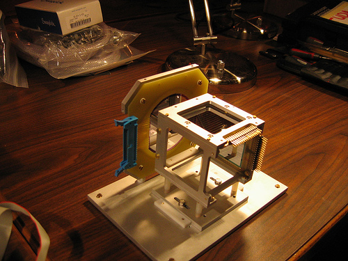
The full detection system consists of a forward-angle S2 detector and a
"barrel" of 4 W1 strip detectors. Below is shown a test installation of an
S2 and 2 W1 counters, before ribbon cables were connected.
Installation of the TUDRAGON chamber
- locate a storage box large enough to handle the standard gas target
box and its coupling flanges and a smaller box to store screws
- vent the standard gas target and disconnect monitor detector cables,
thermocouple lead, capacitive manometer and gas inlet bellows.
- remove the standard gas target chamber by removing the ISO clamps and
removing the screws which attach the end flanges to the differential
pumping boxes. Store the screws in a box for later use. Store the
chamber, side plate and special ISO o-ring flange in the large box.
(The ISO flange has one rim cut back.)
- Mount the two U-shaped support brackets, which should be stored with
the TUDRAGON chamber, on the yellow support frame of the gas target
station. The one with 2 holes in the cross-bar goes upstream, the one
with 1 hole goes downstream. Remove 2 bolts from each side of the "yellow
frame" and attach the brackets using the longer bolts taped to the
brackets. Put the "standard" bolts in a labelled bag in the large box
with the standard target.
- check that no foreign objects are visible at the bottom of the
vertical 6" line to the Roots blowers. Place a standard ISO flange on top
of the vertical 6" line. Clean surfaces of the TUDRAGON outer chamber,
then place it on top of the 6" line. Support clamps under the ISO flange
should limit sideways motion of the box. Put 3 or 4 clamps on the ISO
flange, finger tight.
- Install the short bellows sections which connect the TUDRAGON vacuum
box to the upstream and downstream differential pumping boxes. Re-use the
screws that attached the flange to the differential pumping boxes, but
note that the TUDRAGON box is tapped for metric screws. Tighten the
clamps on the ISO flange.
- Attach the vacuum box to the support brackets, using the spacers and
bolts that were stored with the TUDRAGON chamber. Start with the shim
combinations provided.
- Check that a screen is inside the vacuum box and covering the hole
for the 6" pipe. If it is missing, cover the hole with a temporary plate
to prevent dropped screws from falling down the pipe. Install the
upstream and downstream pumping tubes which restrict gas flow in the
bellows sections. Tighten screws loosely, then finger snug, then with a
key. (Inside surface of the box has a hard-to-remove 0.010" bevel, so do
not tighten one side until the opposite screw is snug.)
- If detectors are mounted on the lid (or not to be in use), put the
inner gas cell on the bench and lower the lid onto it (or place the lid
upside down on the bench and lower the inner gas cell onto the lid) and
bolt them together.
- Mount the short inner pumping tubes on the gas cell.
- Carry the lid and inner cell to the vacuum box and set it on top.
(Make sure the o-ring is in place!) Bolt the lid down.
- Mount the capacitive manometer and attach the gas supply hose to the
KF fittings on lid.
- Follow pump-down procedure as outlined for the standard DRAGON gas
target.
|