


|
 |
How to Operate the Solid
Target System
Overview
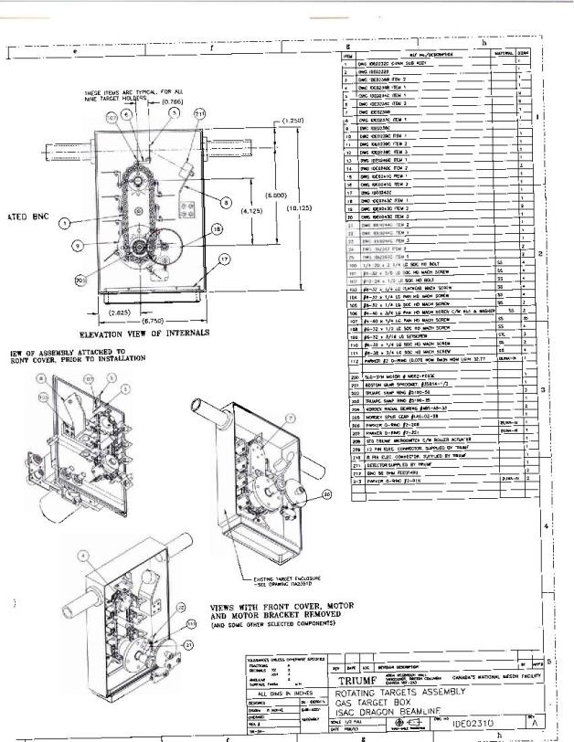
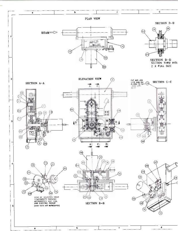
The solid target mounting system allows insertion of any one of 9 solid targets
into the beam at the centre of the DRAGON target box. It is designed to permit
operation of the BGO array in the same way as with the DRAGON gas target.
Accordingly, the target drive mechanism is mounted on a plate which can form one
side of the target box, in exactly the same way as the side-plate which supports
the gas cell.
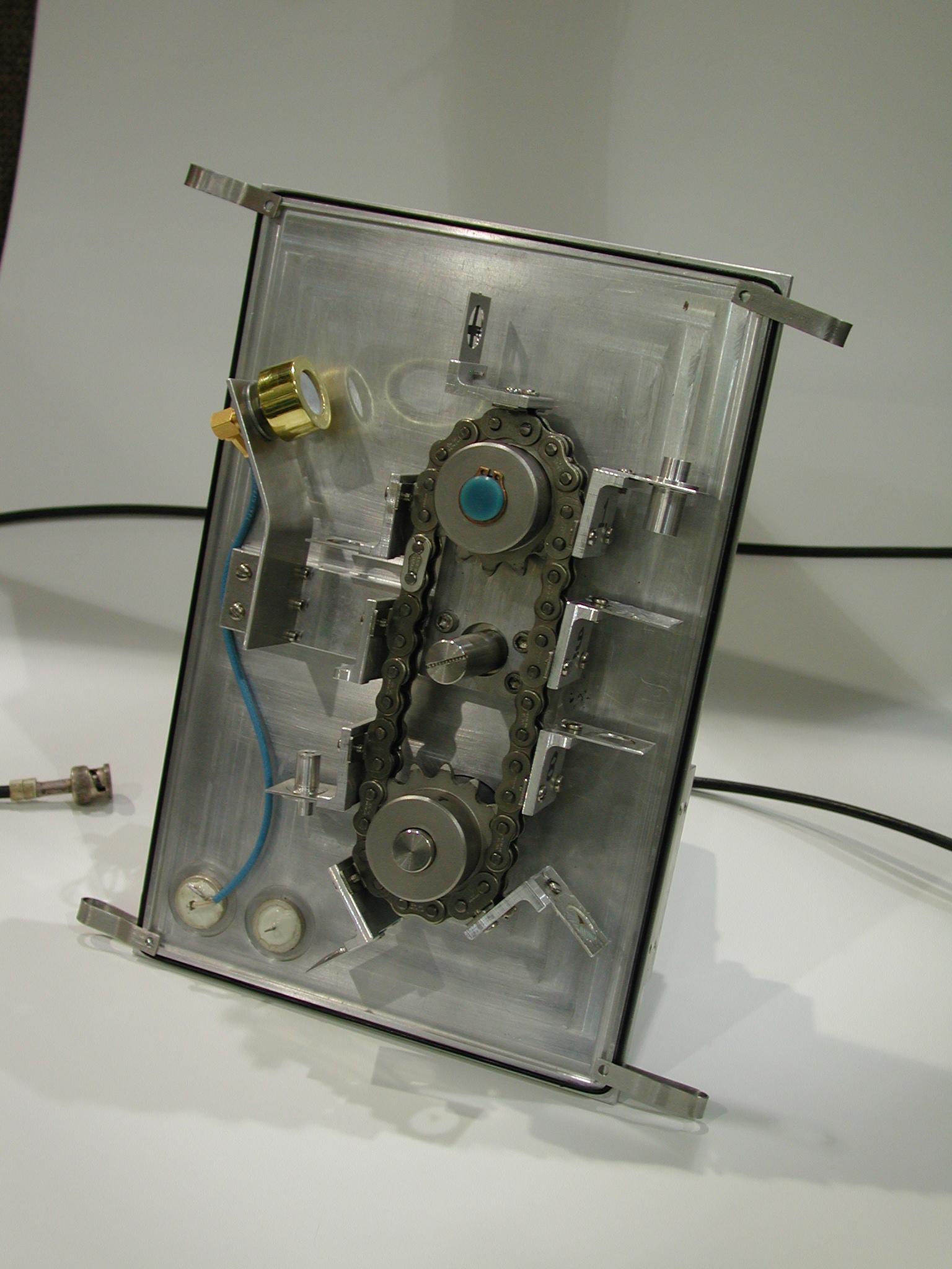
The principal features of the system are:
- stepping motor controllable through EPICS
- coupler and feed-through from the motor to a drive sprocket inside vacuum
- a second gear and chain containing 9 target mounting bases
- cam-actuated microswitch for position calibration
- a Si detector for monitoring beam intensity and target integrity
- electrically insulated target drive for external current readout or application
of bias voltage
- an "ash-tray" to catch debris from broken targets before it drops into
the Roots blowers
If it has been a long time since the solid target ladder was used,
some key pieces may have been mislaid. Before starting the procedure
outlined below, the following should be confirmed:
EPICS control via the SOLTAR button on DRAGON page Optics(1) has been
enabled; target frames of the correct size are available; the rectangular
"ash tray" piece, or equivalent, to block the opening between the target
box and the pumping Manifold is available.
It also is convenient to have clips to hold the target side plate in place prior
to pump-down.
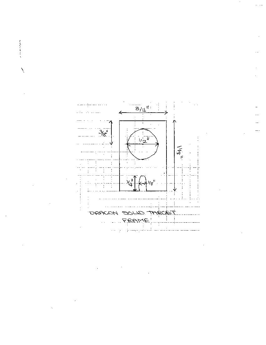
Mounting targets on the drive
Targets should be mounted on frames which fit into the base and which have
the correct base-to-beam distance. They should not be longer (taller)
than the standard frame, to avoid hitting the Si monitor counter or the
inside of the vacuum box. See the AlisonCAD figure below, for key
dimensions.
Mounting the drive system on the
DRAGON target
box To replace the gas target cell with the solid target drive:
- If an Elastic Monitor detector is in use, check that its bias voltage
is off.
- Vent the target system to 1 atmosphere (see Vaccum instructions)
- Crank back the BGO array to give clear access to the target box
- Remove the bellows connection to the gas target side-plate and
blank the bellows off with the brass blank-off (which should have
been stored in the Target Parts box). Lay the loose end of the
bellows on the support for the motor of the adjustable valve.
- Disconnect gauge CMGC and lay it between turbo pumps TP2 and TP4.
Re-clamp the o-ring and T-ring to the gas target capilliary tube
so they don't get lost.
- Remove the gas target side plate. Put its o-ring on the solid
target side plate. Remove the in-board pumping tubes ("A" and
"B" or "C") and put them in the Target Parts box.
- If the solid targets are fragile, vent the Inlet Buffer Tank to 1
atmosphere: close VNT1 and open BYP1, FILLV.
- Cover the hole at the bottom of the target vacuum box with the
"ash-tray". Be sure to orient it as shown by the arrow, to allow
proper seating of the side plate on the vacuum box.
- Rotate the stepping motor by hand to position the most fragile
targets at the bottom positions.
- Use clips (should be stored in the Parts box) to hold the o-ring
at the top corners of the side plate. Two people, each one holding
the o-ring in place at one of the bottom corners, slide the plate
in place, capturing the o-ring at the bottom. Tilt the top of the
plate in place, remove the clips and secure the plate in place.
Use 2 C-clamps on opposite sides of the plate at the edge,
tightened gently (walls are thin!). After successfull pumpdown,
the C-clamps should be replaced by compact clamps, attached to
strings, at a height that will miss the BGO array tables..
- Pump down. If the targets are fragile, it is important to have
BYP1 and FILLV open so that the capacitive manometer CMBT in the Inlet
Buffer Tank can be used to monitor the rate of pumpdown.
- Close the manual "Varian" valve located between GOT1V and GOT2V,
located on the upstream side, north-east corner of the gas-target
platform. It is labelled MV-sloR.
- With roughing pump RP1 on, valve RV5 open and RV2 closed, open
valves GOT1V and GOT2V. While one person watches the pressure at
CMBT, a second person should slowly open the manual valve until a
pumpdown rate of about 1 Torr/second is achieved.
- Adjust the manual valve from time to time to maintain the pumping
rate. Below 100 Torr, pressure may be read on CMTRIN as well. When
the pressure falls below 10 Torr, RV2 may be opened and the Roots
Blowers (RB1B, RB1A, RB2A, RB1, RB2) turned on.
- Pressure at CMTRIN should quickly drop to 0.5-0.8 Torr. If it
doesn't, there may be a problem with the seating of the side plate on
the target box: check that there is not a gap at any point where they
meet.
- Start turbo pumps and when they are up to speed (icons change
from dark green to light green) turn on ion gauges IGU3 and IGD4.
- Connect the motor control cables. They should pass above
the BGO carriage, to allow proper closure of
the BGO array. Connect the Si detector pre-amp cable to the
right-most BNC connector on the side plate and provide strain
relief to support the weight of the pre-amp+heavy cables.
Connect the current readout to the bias-box/integrator line.
- Check the motor drive. Do "Calibrate" and then try at least one
other target position. When vacuum is good, turn on IGU3, IGD4
open valve IV11 and check position of a small-aperture target
by viewing with the CCD camera.
- With one person cranking/watching and a second person watching for
collision, slowly crank the BGO array carriage in until it
reaches the stop-bars.
Target selection via EPICS
Select from DRAGON's EPICS menu Optics|Optics(1)|SOLTAR.
(It's at the lower right of Optics(1).) The CALIB button will drive
the target chain to the Target I position. Other targets are indicated
by the Roman numeral immediately to the right of the word "Target".
Click on the appropriate button and you should see the destination number
(black) change immediately, while the numbers in blue indicate progress
towards the destination.
Before mounting the solid target system on the target box, it is important
that a good record be made of which target is mounted in which location.
Due to a glitch, if the DRAGON IOC
is rebooted, some of the numbers in the stepping motor control get set
wrong. The symptom will be that the chain goes around about two complete
turns when the requested change is only one target. To get the correct
operation, select on the DRAGON EPICS menu Diagnostics|Motor diagnostics|
Solid target. Under CALIBRATION the value should be 133.81 mm/rev and
12.70 mm/sec; under Step size -800 for min value and 800 for max val.
(See /home/dragon/soltarnumbers.ps for a display of correct settings.)
Viewing targets with the CCD camera
The "available light" from ion gauges is enough to provide information
about the selected target, provided there are no intervening obstructions
(gate valves or Faraday cups). The best back-lighting comes from IGU3
when gate valve HEBT2:IV8 is closed, but when IV8 is open (and HEBT2:FC4 is
out!) useful light comes from HEBT2:IG2 in 5-10 second exposure times.
Some observables:
- Position of collimator hole, for beam tuning. (Due to the offset
between the plane of the target frame and the point of attachment to the
chain, the proper in-beam position is not the highest point attained
by a target when moving between target positions.)
- Integrity of thin C targets. The intensity of light scattered off IV8
and passing through a thin (brownish, but "transparent") C target was
observed to be only 20% of the transmission through an empty target frame.
Calibration of light attenuation when the target is known to be intact
should allow rapid checks of target whole-someness later.
- Scintillation induced by beam. It has been found that at
multi-nanoAmp intensities an ordinary microscope glass slide will give off
enough light to be visible on the CCD; a slide fragment with a thin carbon
layer to prevent charge buildup has been glued to one of the target
frames. At 50 particle nA of 12C beam, a 40 ug/cm^2 C target gets hot
enough at the centre to make a visible incandescent glow. Light has been
observed from thin mylar films, but only temporarily as they melt!
- "Cross-hair" alignment target. A crude alignment target was made by
stretching two thin strips of black tape across a blank target frame. The
strips are off centre, such that the intersection of their two edges
marks the centre of the target frame. Two indentations, one on the edge
of each
strip, indicate which pair of strip edges define the centre-lines.
Venting the solid target system to 1 atmosphere
If the targets are fragile, slow venting is required and the usual
venting procedure should be replaced by the following:
- Close isolation valves IV8 and IV11. Turn off the ion gauges
IGD4 and IGU3. Turn off the turbo pumps and the Roots blowers.
Close RV2. From the pumpdown stage, the Inlet Buffer Tank should be
at low pressure (read on CMBT). (If it is not, pump it out via RV4
and RV5; open FILLV, close RV4 and open BYP1.)
- Call a gas target Expert and have them bypass the interlock on the vent valve VNT1.
Ask them to explain the possible consequences of a bypassed interlock.
- Wait 15 minutes for (partial?) turbo spin-down
- Close the (unknown to EPICS!) manual valve in series with VNT1.
It is under the gas-target platform, identified by a pink ribbon.
Access to it is gained by removing the mobile stairs which give access
to the south-west side of the platform and reaching across a box fan
towards the beamline, at the downstream edge of the platform.
- Open VNT1. Slowly open the manual valve (of order 1/4 turn)
until pressure rise is noted on CMTRIN and CM1. If the pressure rises
above 1 Torr, close VNT1. If a rattling sound is heard at the target,
close VNT1.
- As the turbos spin down, you may see the pressure at CMTRIN
and/or CM1 fall, even though VNT1 is still open. This signals that
the turbo spin-down has reached a point where they are no longer
compressing gas into the volumes sensed by CMTRIN/CM1.
- Supply dry nitrogen gas to the venting line: at the south side
of magnet MD2 is a cylinder of compressed dry nitrogen. Ensure that
the hand valves "LN2 dewar pressure" and "Separator vent" are
closed. Open the valve on top of the gas cylinder; the right-hand
gauge should indicate 100's of PSI pressure. If the left-hand gauge
indicates a reduced pressure greater than 0, turn the reduction-valve
knob counter-clockwise several turns. Open "Separator vent" hand
valve; pressure indication on the left-hand gauge should drop quickly;
if it does not, turn the knob further counter-clockwise until the
reading does drop.
- Turn the pressure-reduction knob clockwise until a reading near 0
is obtained.
- Open VNT1 and monitor the rate of pressure rise at CMBT. Adjust
the manual valve in series with VNT1 to achieve pressure increase of
about 1 Torr/second.
- When CMBT gets close to 750 Torr, pressure rise may stall. Try
adjusting the reduction valve at the gas cylinder to be slightly above
0.
- When CMBT reaches 760 Torr. close VNT1. Close the valve on top
of the N2 gas cylinder, turn the reduction valve ccw and close
"Separator vent" valve. This is important: otherwise a whole cylinder
of gas will bleed away if you forget to do this.
- Pull back the BGO arrays
to give access to the target side-plate. Disconnect the motor drive
cables. Slip a C-clamp so that it sits atop the target vacuum box,
adjusted loosely so that it can prevent the plate from falling away
when the special clamps near the bottom of the plate are loosened.
- Gently break the seal between side plate and the rest of the box.
Carry the plate to a convenient working area (table), avoiding fans
and other sources of strong air currents.
Dave Hutcheon
8 August, 2005
27 March 2019
|