|
User's Manual for Tuning the DRAGON Separator
Revision history
| Version |
Author |
Description |
Date |
| 1.0 |
D.A. Hutcheon |
Initial document |
14 January 2003 |
| 1.1 |
D.A. Hutcheon |
Update to beam centering procedure |
24 March 2003 |
| 1.2 |
A. Olin |
Update regarding saving tunes for -1% scaling |
10 April 2004 |
| 1.3 |
C. Ruiz |
Updated new tune scaling instructions |
16 April 2004 |
| 1.4 |
D. Hutcheon |
At Mass slits: calculate A/q from B(MD1)^2 / V(ED1) |
13 May 2004 |
| 1.5 |
D. Hutcheon |
Final XSLITC centring with Scaling Energy |
17 June 2004 |
| 1.5 |
D. Hutcheon |
Tuning: setting MD2 field |
12 May 2005 |
| 2.0 | D. Hutcheon |
Decadal update | 26 March 2019 |
Contents
- Introduction and Warning
- Scaling
- Loading a previous tune
- Saving a tune
- Centering the beam through the target
- Beam position and angle at the windowless gas target
- Troubleshooting
- Tuning beam through the separator
- Tuning from charge slits to mass slits
- Tuning from mass slits to final slits
- Tuning the separator for recoil ions
- Change of selected charge state
- General Troubleshooting
By following the instructions in this document, a user can ensure that the
beam has been properly centred on the target and that the elements of the
electromagnetic mass separator have been tuned for optimum transmission of
the desired recoil ions and rejection of the unwanted beam particles.
It is assumed that the user has some familiarity with the EPICS control
system and the general properties of magnets, electrostatic dipoles, slits
and Faraday cups. Detailed description of these devices and of the
separator vacuum system are provided in other documents.
Warning: When the End Detector of recoil ions is a solid state
device (e.g. double-sided silicon strip detector, DSSSD), care must be
taken to avoid transmitting beam through the separator and onto the
detector. At typical beam intensities, transmission of as little as 1%
of the beam for a fraction of 1 second will be enough to damage a
DSSSD. Insert the final Faraday cup, FCF, before doing any tuning of
beam through the separator. Check that there is no measurable beam
current on FCF before pulling it Out.
To use Tune Scaling, it is essential to read from file a tune which is
known to be "good" - to have the desired focus
properties.
Saved tunes are named according to date and time of their creation. If
you do not know the date/time of a "good" tune (either from memory or a
previous logbook entry), consult someone who does. If this is not
possible, use the settings in Tables 1 and
and 2 multiplied by the MD1 field or current (obtained
by measuring the post-target beam energy as described below - for the
energy measure to have been valid, Q1 and Q2 fields must have been set in
the correct ratio to MD1 field).
Table 1: Magnet field ratios for a standard DRAGON tune.
| Magnet |
Field ratio |
| Q1 |
0.709 |
| Q2 |
0.677 |
| MD1 |
1.000 |
| Q3 |
0.553 |
| Q4 |
0.735 |
| Q5 |
0.381 |
| Q6 |
0.366 |
| Q7 |
0.512 |
| MD2 |
1.230 |
| Q8 |
0.387 |
| Q9 |
0.238 |
| Q10 |
0.266 |
Table 2: Setpoint current ratios for a standard DRAGON tune.
| Magnet |
Setpoint ratio |
| SX1 |
0.0528 |
| SX2 |
0.0112 |
| MD1 |
1.000 |
| SX3 |
0.0100 |
| SX4 |
0.0974 |
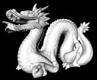
The new scaling program is selected by choosing
"New Scaling"
from the "optics" drop-down menu on the EPICS toolbar.
If a new DRAGON tune is required, follow the instructions for
"Tuning beam through separator"
(section 4.), then follow steps A-I below.
If scaling from a previous tune, proceed from step F.
A. Saving a Tune.
It is assumed that at this point the beam has been tuned all the way to FCF,
so that the MD�s and ED�s and all quads and steerers have their
required values. You should be in "E/q/m" mode.
The saved tune is necessary so that when an energy change or charge state change
is made, all the elements, including steerers are adjusted accordingly.
Before saving a tune, you must be made sure that the beam energy after the target
as calculated by the MD1 NMR field reading ( and using the relation
E (keV/u) = 0.0004817(qB/m)2 ) has been entered into the top line of the
right-hand side of the scaling window, and ENTER has been pushed. This can
be done with the "Calc E from NMR" button.
Also check that the following field ratios are correct:
Q1/MD1 = 0.709
Q2/MD1 = 0.677
DO NOT press Apply Scaled Tune here. If you do, you will lose your
beam tune because you scale these values from the reference tune.
B. Click on the "Save tune as reference" button.
This brings up a window called "Reference Tune Parameters"
which has a button at the top called "Get scaled values",
has a few lines for comments, and has a button at the bottom called
"Save current tune as reference".
C. Click on "Get scaled values".
This gets the current values of all the electromagnetic element settings,
and also gets the current value of the Energy, charge and mass, which are
as displayed in the right hand section of the scaling window (check that this is so).
D. Enter Comments.
Enter any explanatory comments about the tune
E. Click "Save current tune as reference".
The left-hand section of the scaling page, under the heading
"Reference Parameters", should read:
a) The energy (of the recoil) as in the top line of the right-hand section.
b) The mass and charge of the particle, as in the right-hand section.
c) The ED1 and ED2 setpoint values as read from optics pages 2 and 4.
If this is not so, then there is a problem and a previous step has been missed or performed
incorrectly.
If this is OK, then the tune has been saved correctly.
It is now necessary to reload the just saved tune back into the scaling page:
F. Click "Select Reference Tune".
Select the just saved tune.
The values in the right-hand page should now all be the same as the values on the left-hand page,
if they are not, then the new tune has not been selected correctly and the scaling will be based
on incorrect values.
G. If it is desired to change from beam to recoil or recoil to beam,
select the "Beam <-> Recoil" mode and
change the particle mass.
H. If a nominal (0%) tune is
required, click "Apply scaled tune".
I. If a (-1%) tune is required,
enter the new energy value into the top line of the right-hand side, hit ENTER, and then click
"Apply scaled tune".
To compensate
for hysteresis adjust MD1 and MD2 currents to match the NMR values on
the scaling page.
The DRAGON separator now has the new tune saved and loaded.
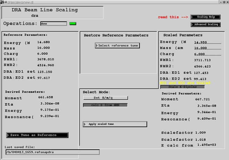
Figure 1: The beam line scaling screen in EPICS
The beam should be centred in the horizontal (x) and vertical (y), in both
position and direction, at the middle ("z=0") of the target. This is
important for 3 reasons: it optimizes transmission of the desired recoil
ions; it minimizes aberrations, which reduces beam spotsize at the
rejection slits; x-position of the beam at the target affects the apparent
beam energy when it is measured using MD1.
When quadrupoles Q1 and Q2 are On at normal strength
(according to the ratios of Table 1, they produce at the
Charge slits following MD1 (XSLITC, YSLITC) an image of the beamspot at
the middle of the target. The linear magnification is -0.44 in x and -3.5
in y. When Q1 and Q2 are Off, the beam position at the Charge slits
depends on the initial direction of the beam as well: to a fair
approximation, the beam behaves as though it has travelled through a 3-m
drift space between target and Charge slits (assuming MD1 field has been
set to the magnetic rigidity of the beam). Thus, by alternating between
"quads On" and "quads Off" it is possible to measure beam position and
direction at the target.
If Tune Scaling is used to set Q1, Q2 and MD1, use the "Apply scaled tune
(up to MD1)" option.
- Locate the 6-mm gas cell aperture in the CCD (if not already known)
- Gas target pumps must be running, so ion gauge IGU3 can be turned on
- Valve HEB2:IV8 must be closed, DRA:IV11 open
- Run a 10-second exposure on the CCD in Focus mode (see CCD instructions.)
A light circle should be visible: this is light from IGU3 that has reflected off
valve IV8 and come through the 6-mm aperture of the gas cell. Set a Subframe for
Width = Height = 150 pixels, centered on the 6-mm aperture.
- Use the View|Information feature to find the pixel coordinates of
the 6-mm aperture. Record them.
- Allow Operations to tune beam through to FCCH in their traditional
fashion (to maximize transmission through the target cell),
with gas removed by having both BYP1 and
OVTR1 valves closed. (Remember to open IV8.)
- Put gas in the target, and adjust MD1 to centre beam
at XSLITC. (Q1 and Q2 on.) If the MD1 NMR does not lock, adjust
the magnetometer
adjustment bar under the MD1 current set adjustment - to lock it.
- Calculate beam energy from the MD1 NMR value. If it is not within a
range acceptable to this experiment, inform the Operator and tell them the
amount by which it must be changed. Go back 2 giant steps.
- Insert profile monitor PROFCH
(icon between
MD1 and XSLITC on Optics(1) page). The resolution is 1 mm per channel
in X and 2 mm per channel in Y. In this mode each 1 mrad the
beam is off-axis at
the gas target results in a shift of about 3 mm at PROFCH.
- Observe beamspot on CCD display. Confirm that Operations are able to see the CCD
display and the Profile Monitor display.
- Turn off Q1 and Q2. Profiles will broaden at the Profile Monitor,
but centroids should not shift if the beam is going straight along the
beam axis at the gas target.
- If the beamspot is more than 10 CCD pixels away from the centre of the
gas
cell or the profile monitor position was > 3 channels in x or 1.5
channels in y, have the
Operator adjust the beam
- When beam is centred in position and angle at the gas target, turn
Q1 and Q2 back on to confirm the quad On/Off centroids don't shift.
- Retract Profile Monitor and close down XSLITC to 2mm to
measure beam energy (Gas In or No-Gas, as
desired). Make sure XSLITC is at Position=0. Check the Linear Scales values
to confirm that EPICS hasn't been confused by action of the anti-collision
switch. If in doubt, hit the calibrate buttons for the slits before taking an
accurate energy measurement.)
- Document beam properties. Make a screen-grab of the CCD picture
(or equivalent documentation).
Figure 2: A typical desktop configuration to adopt
when tuning the beam.
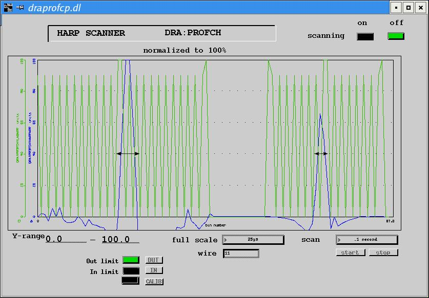
Figure 3: "Typical" profile monitor image with
Q1,Q2 on. The black arrows indicate the range of Quads-Off
centroid shifts corresponding to less than 1 mrad misalignment of
beam at the gas target.
- Beam disappears before the operator's adjustments have put the beam on
centre: may be due to severe "porpoising" of the beam through HEB2.
Suggest to the Operator to check the YCB's after the DTL and before
HEB2 to see if any is on hard. If so, a tune may be improved by
reducing early vertical steering and re-centring on the beamline
harp monitors.
- Beam disappears when doing the horizontal adjustments (XCB6 et al.).
This is even more complicated than in the vertical because the
"slaloming" can involve the 22.5 degree benders as well as the
XCB's.
No magic formula here, though it's probably a good idea to start with
XCB's off or low.
After the beam has been centred at the target and its post-target energy
has been measured, the rest of the separator elements may be set to a
"tune": dipoles and steerers set to transport ions of a certain mass,
charge and energy down the ion-optic axis; quadrupoles set to confine the
desired ions and to focus the beam and recoils at selection
slits; sextupoles set to reduce higher-order aberrations. The EPICS page
for DRAGON Optics has a "Tune scaling" utility which calculates and sets
the elements for a certain mass, charge and energy of ion, scaled from a
"Reference Tune".
- On the Tune Scaling page, "Select reference tune" (provided you
know the name of a "good" tune). With options "Scale E-dipoles" and
"Scale Energy", set the "Scaled parameters" to match the beam mass,
post-target energy and the selected charge state.
Observe the calculated high voltages on the electrostatic dipoles ED1 and
ED2: if they are higher than the voltages to which the ED's have been
conditioned, it will be necessary first to do voltage conditioning (see
Users' Manual for Separator Hardware).
"Apply scaled tune" and watch for Operations box to change from "..." to
"done". With XSLITC at Position=0, Width=2mm check that the beam is centred on
XSLITC. If there is more beam on the Left slit than the Right, increase
the "Energy" scaled parameter and "Apply scaled tune" again.
If the Right slit has more beam than the Left, Energy parameter must be
decreased. Iterate until the beam is centred on XSLITC.
Do not simply adjust MD1 current directly. This will cause the nominal
beam energy to get out of sync with the true energy as calculated from the
MD1 NMR, and MD1 to get out of step with the quad/sextupole fields. The
error could propagate to any saved tune.
- Check that all electromagnetic elements are On: scan through
each
of the EPICS Optics pages (1 through 4) to see that the icons are green,
that MD1 and MD2 NMR units have locked on the resonance (readings are
blue, not white) and that quadrupole Hall probe readings are reasonable
(look for status buttons to be green, not yellow, and for readings to be
reasonably close to the ratios of Table 1).
- Check again that final Faraday cup FCF is In. Put FCM In (page
Optics (2)) and take FCCH out. Make sure the MCPs are out.
- Put BCM2 In, set the range to the most sensitive one which doesn't
saturate (reading below 0.98 on all of the quadrant currents). Use
steering magnet SM1X (immediately downstream of FCCH) to centre the beam
horizontally on BCM2. Use SM1Y for vertical centring. Provided the beam
was properly centred at the target, very little current should be required
to centre on BCM2 compared to full-scale current of 5 amps; need for
large currents on SM1X or SM1Y may indicate a readout problem with one
or more of the quadrants on BCM2.
- Pull BCM2 Out, open the Mass slits XSLITM, YSLITM to Width 25 mm
each and look for beam current on cup FCM. If current is seen on one of
the slits but not FCM, adjust ED1: increase ED1 if current is on the Left
slit, decrease ED1 if current is on the Right slit. (If ED1 high-voltage
readback does not stabilize on the new setting, check for signs of
conditioning.)
- When current is seen on FCM, progressively reduce the Width of
XSLITM and adjust ED1 to centre the beam, until Width = 2mm is reached.
- Check that the Mass/Charge ratio of the ions (A/q) is what you
expect by comparing the ED1 setpoint voltage in kV (V) and the MD1 field
value in Tesla (B) using the formula
A/q = 2468 (B2)/V
(The difference from the theoretical value 2412 is attributed to the
ED1 HV power supply calibration. The constant may vary if the power
supply is replaced after the time of writing (13 May 2004).) Deviations
from the expected ratio by amounts of order 0.5% may be expected.
- Open XSLITM to Width = 15 mm. Close YSLITM to Width = 3 mm and
adjust SM1Y to centre the beam. Open YSLITM to Width = 25 mm.
- From DRAGON Optics(3), pull FCM Out, put In BCM3 and set to an
appropriate current range. Adjust SM2X and SM2Y to centre the beam on
BCM3. (Full scale on SM2 is 5 amp.) Pull Out BCM3.
- Adjust the MD2 current so that the ratio of magnetic
fields B(MD1)/B(MD2) measured by the NMR's is 0.813.
- Put In BCM4 and adjust SM2Y for vertical centring. The beam may be to
the right of centre on BCM4; if so, adjust MD2 to centre it. Pull Out
BCM4.
- From Optics(4) put In BCM5 and adjust SM3Y for vertical centring.
Use SM3X for horizontal centring, provided its setting is small compared
to full scale (100 amp). If more than approx. 15 amps is needed on SM3X,
make a small adjustment to MD2 to centre on BCM5, instead. Pull Out BCM5.
- Put In BCM6 and use SM3Y to centre the beam vertically. Pull Out
BCM6.
- Turn SM4X to 0 and use ED2 to centre beam as slit XSLITF is closed
progressively to Width 2mm. Open XSLITF to 45 mm. Use SM4Y to centre
beam as YSLITF is closed to Width 2mm. Open YSLITF to 45mm.
- Compare beam currents at FCCH, FCM and FCF to confirm that beam
transmission is approx. 100%.
Save the tune, as described in the section on Scaling, remembering to update
the reference E/m/q to their current values.
Provided the beam tune has been saved and made the new reference tune, in
the Tune Scaling page change "Scale E/m/q" to "Beam<->Recoil", change
the Scaled Parameter to the mass of the Recoil and "Apply scaled tune".
The voltages on the ED's should change by the ratio of masses of
Beam/Recoils. The magnet settings should not change.
If a scaled recoil tune is requested, go to "Scale E/m/q" mode and modify the
energy. Because of hysteresis adjust MD1 and MD2 NMR's to the value given
on the tunescale page.
Beam current on FCF should drop below a measurable level. If so, it
should be safe to pull Out FCF while watching the End detector count-rate
monitor. Do not pull Out FCF if measurable current remains after
tuning for Recoils.
On the Tune Scaling page, enter the new value
for the Reference Parameter Charge. Look at the new ED1 and ED2 settings
listed below the Reference Parameters, to confirm that they are within
the range for which the ED's have been conditioned. If so, "Apply scaled
tune". If not, the selected charge state cannot be used.
|