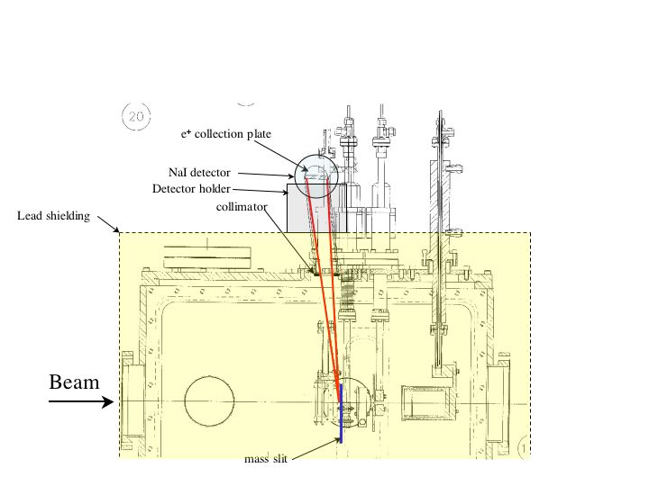
The original purpose of this detector pair was to monitor the content of 26mAl in the 26Al beam. It was last used for the 19Ne(p,g) beam time. When DRAGON is set to transmit recoils from the 26Al(p,g)27Si reaction, the A=26 contaminants are deposited on the left mass slit at a distance of 0.69" from the beam axis. For practical reasons, the NaI detectors are placed on the lead shield surrounding the mass slit box. A positron catcher assembly, or "horn", was designed to allow positrons from the decay of 26mAl to be collected in the tip of the horn, and the NaI detectors measure the 511 keV annihilation gamma rays created when the positrons are stopped by the collection plate. In general, this can work as a beam monitor when measuring (p,gamma) reactions with short-lived positron emitters AND the separator is set to transmit recoils. Obviously, it depends on the half-life of the beam; this doesn't work for 26Al, but would work for isotopes with ~second half-lives.
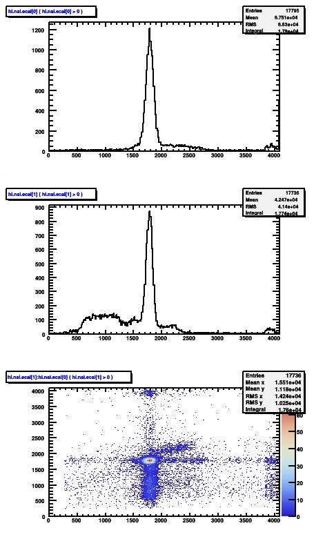
The associated electronics only generate a "heavy ion" trigger when there is a coincidence between the two detectors. Energy signals are read from each detector and recorded (in PAW) in two singles histograms as well as a 2D histogram. A scaler records the raw rate of coincidence. In addition, the random coincidence rate is measured by observing the coincidence between NaI1 and a delayed copy of NaI2.
The figure below shows the horn assembly and detectors as mounted on the mass slit box. A collimator is used to match the positron emission cone defined by the point on the mass slits and the smallest dimension on the catcher plate at the tip of the horn. The detectors sit in holders on top of the lead shielding box on both sides (beam left and beam right) of the horn. The NaI detectors are 3" diameter by 3" long NaI crystals (this may change in the future as these are borrowed from SFU).
B. Detector Operation
The detectors are biased to +900V through the LeCroy High Voltage controller located to the north (left) and outside of the "ED1 West" gate. The HV is supplied on channels 8 and 9 of this power supply.
After locating power supply, make sure the supply is on by pressing "HV ON" button.
Press and hold the "C"(hannel) button and scroll with the arrow buttons until 8 is displayed.
Press the "V"(oltage) button to determine that channel's setpoint.
If it reads 900, press "C" and up arrow until channel 9 is selected.
If it reads 900 also, press "restore".
If either read zero, for EACH channel, press and hold "V" button while pressing and holding the up arrow key until the meter reads 900.