Procedure for floating and installing ultra-thin DLC MCP foils
The MCPs are not mounted inside the beam pass directly. Instead they detect
secondary electrons, which are emitted when the beam passes through thin
carbon foils. The secondary electrons are then deflected into the MCPs by
setting wire planes to the required potentials. In order to maximize
the flight path, MCP0 detects electrons from the downstream side of the foil
whereas MCP1 is mounted backwards detecting the electrons from the upstream
side.
Since MCP0 is located close to the achromatic focus (10 cm upstream), it is
smaller (diameter of MCP0 40 mm) than MCP1. Carbon foil diameters between
15 and 40 mm can be used. MCP1 is roughly twice the size of MCP0 and can
therefore also detect all recoils with a large divergence as in reactions with low
mass, low energy and high reaction Q-value. The carbon foil for MCP1 has a
diameter of 70 mm, the MCP detector itself has a diameter of 75 mm.
Making large enough, flat carbon foils is rather challenging and requires steady
hands and patience. The required (typically 4-5 µg/cm2
thick) diamond-like carbon (DLC) foils are produced at TRIUMF by MicroMatter Technologies Inc. in Surrey, BC via laser ablation of carbon and need to be very homogeneous and pinhole-free DLC foils in order for them to be floated without
ripping apart. Note, that the thickness of the foil is a compromise between
the number of electrons produced per incoming beam particle and the desired minimal energy loss as well as angular straggling.
The recommended procedure on how to successfully float the carbon foils and subsequently apply them
to a Ni-plated support mesh with high enough transmission (98% and 95% for MCP0 and MCP1, respectively) is described in the following.
Preparation
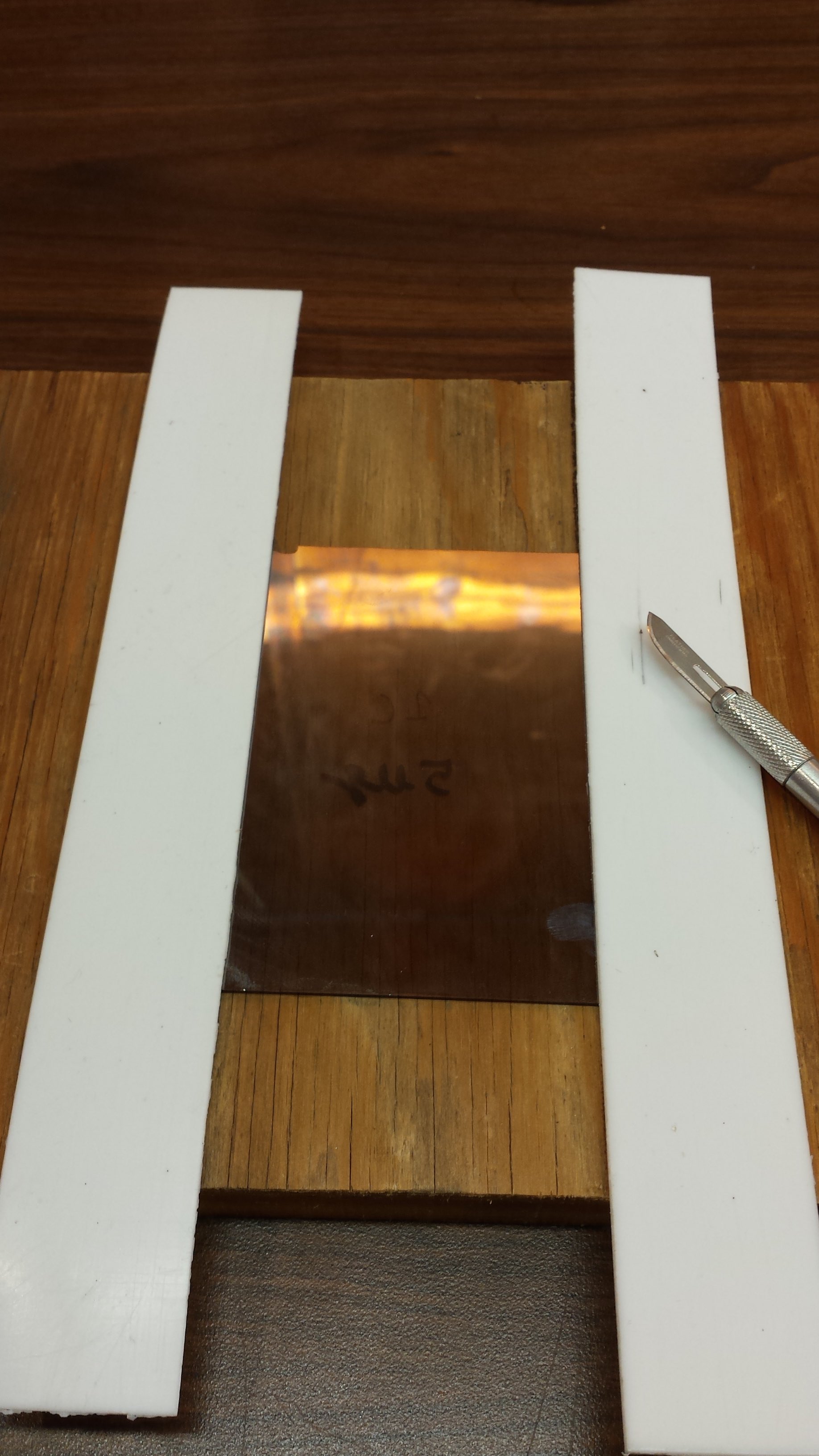
Before floating the foils, it is recommended to cut of a few mm from the upper
and lower edges of the foil, as this allows easier detachment of the foil from the
small glass frame they are initially attached on. You require:
A sharp razor blade
A support pad (i. e., wood or plastic)
A ruler, or a long, straight edge to cut along
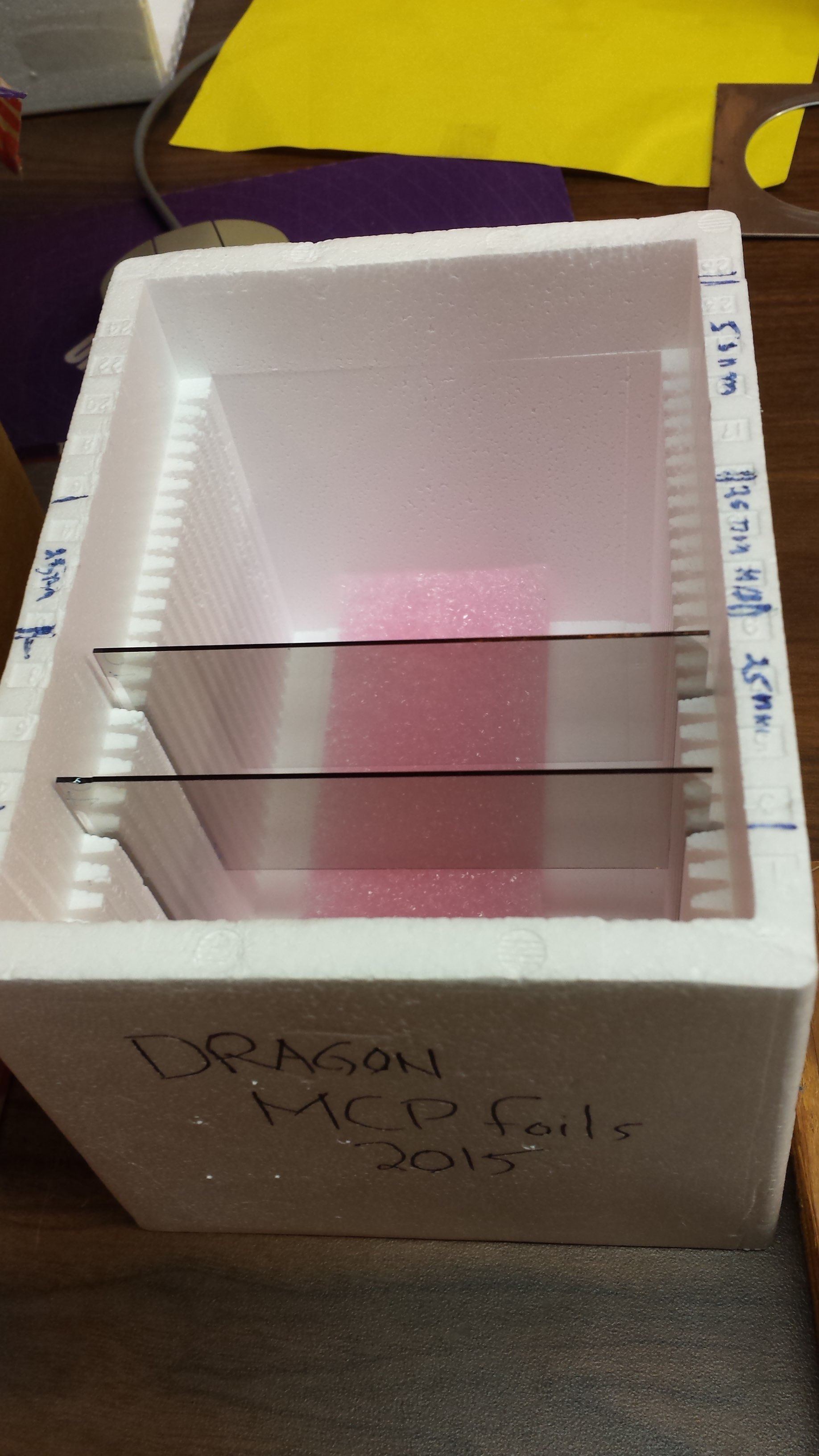
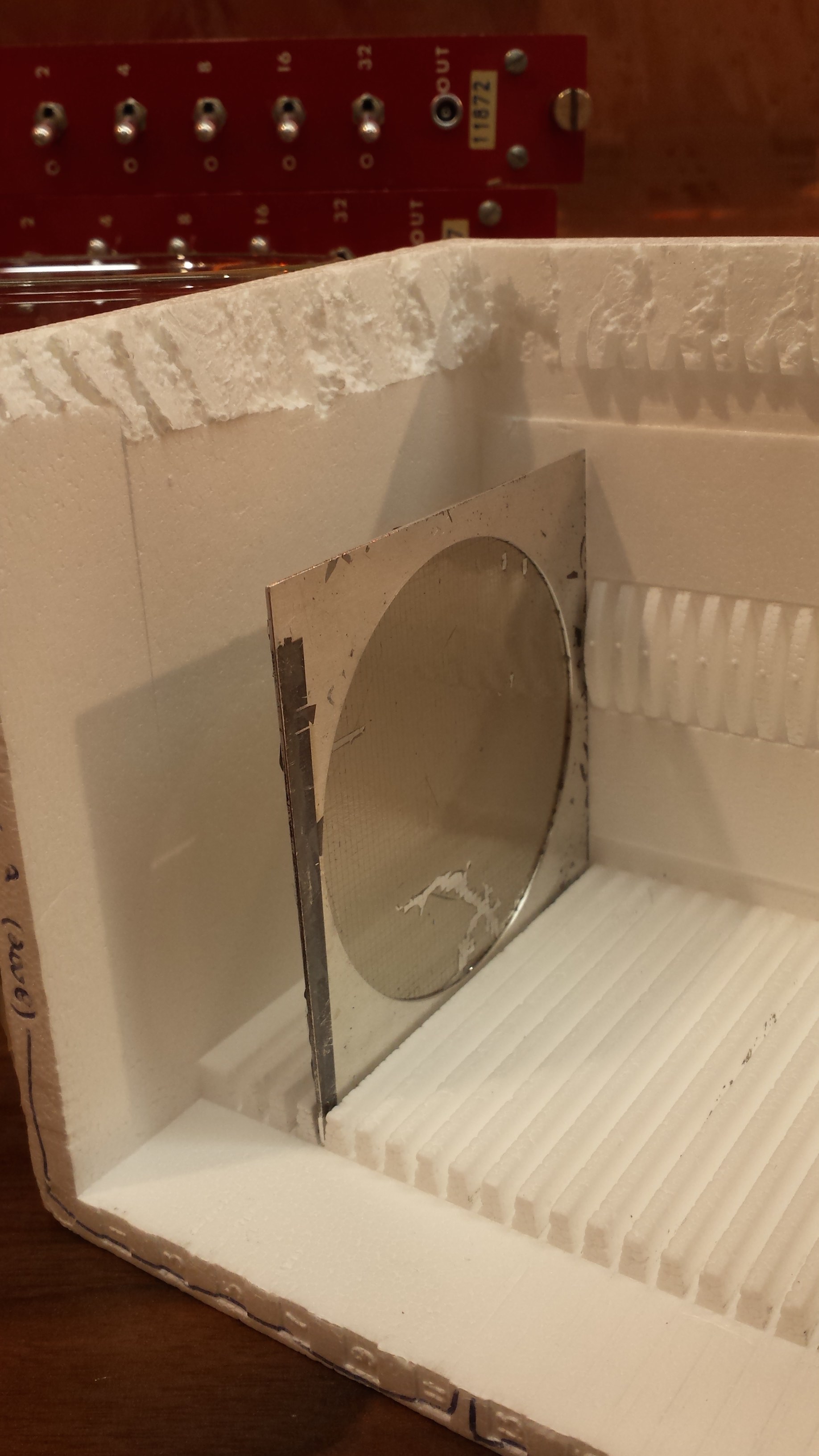
Carefully take the foils out of the styrofoam casing (see Fig. 1). In any
case DO NOT TOUCH the side of the frame with the carbon. Usually, the
glass frames have a label (for instance "1C"), which is written on the glass side
without the carbon, so you want to place the frame with the glass side on the
support pad (compare Fig. 2).
Fig.1 - MCP foils on glass in styrofoam casing.
Fig.2 - Prepared setup to cut edges of the foil before floating.
Now place the ruler on the upper side of the foil and cut of a few mm (the less material is cut off, the less will float around in the water basin later and potentially catch the main foil, which could destroy it!)
and repeat the procedure on the lower end of the foil. If the foil has evident tears on either of the long edges, you may want to cut along those sides as well.
Otherwise, you can leave them as they are.
Setup and floating
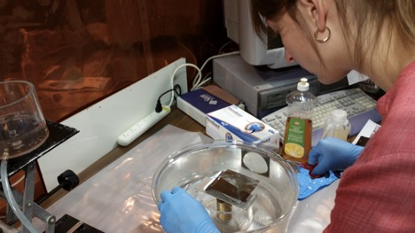
Before floating foils, be sure to be in an environment with minimal air movement (ideally a clean lab, but avoid areas with strong air circulation). The foils
are extremely fragile, so never touch them or breath on them.
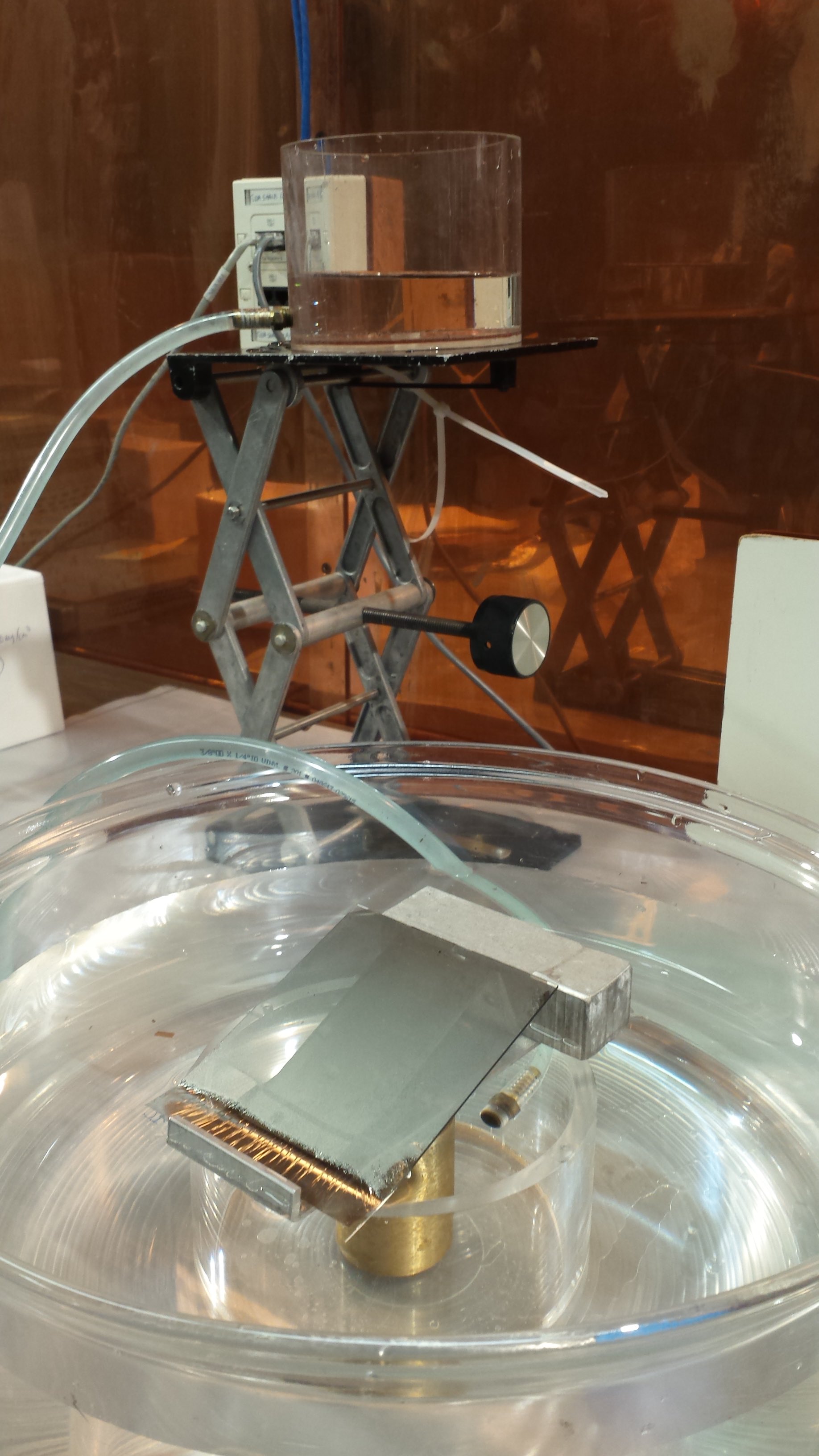
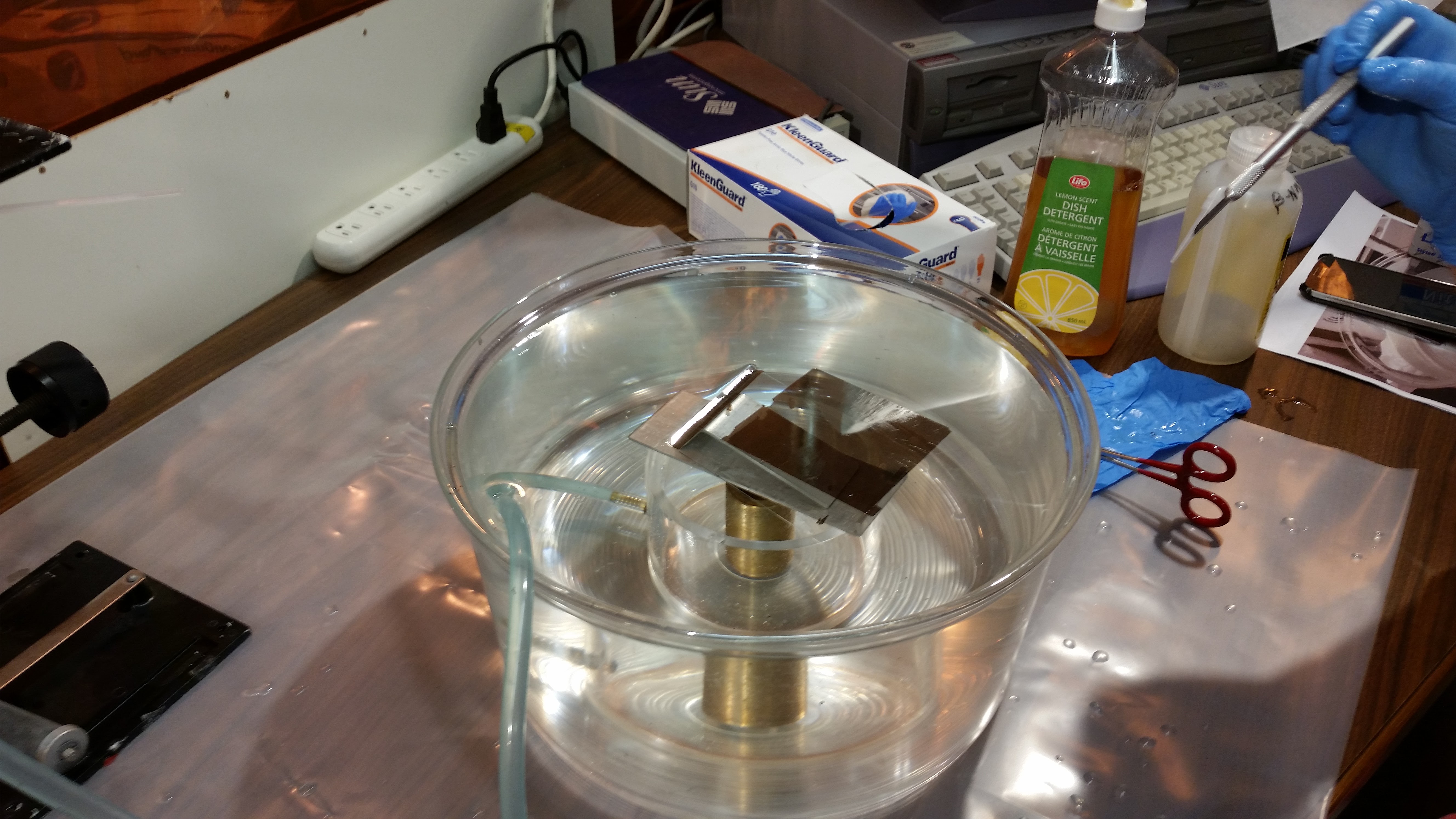
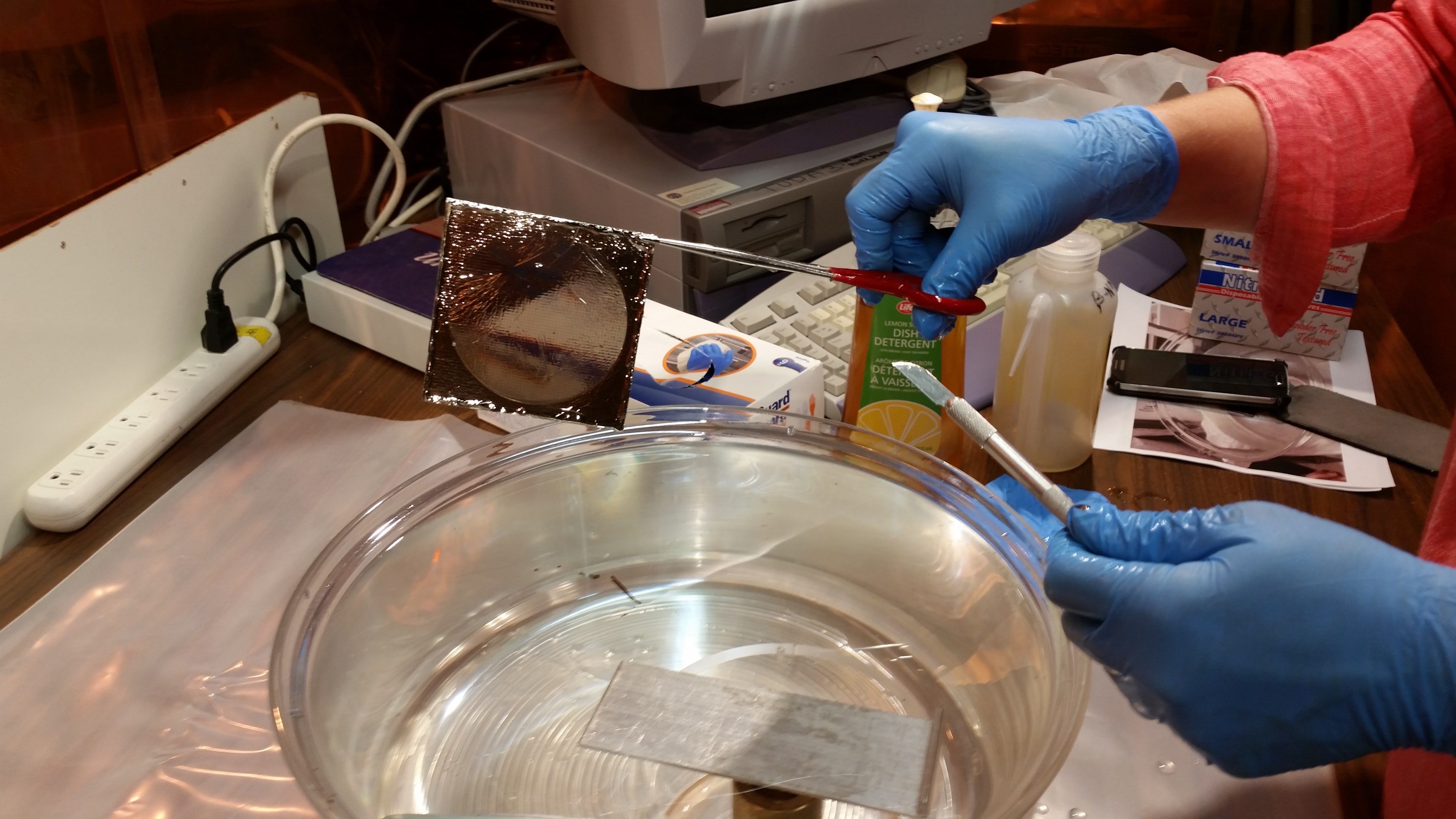
The setup as shown in Fig. 3 consists of:
a big water basin on a steady table
two smaller basins, which act as a flow regulator to slowly adjust the water level
an adjustable stand to place one basin on a higher level
a heavy cylinder (or something similar) to weight down one small basin which is placed inside of the large basin
an elbow shaped piece to balance the glass frame in a 45° angle
a small block to hold the elbow into place
a plate, with one bend edge to hold the glass frame into place
a razor blade and dish soap
a pair of latchable tweezers/forceps to catch the foil
a frame with Ni-mesh
a carbon "foil" on glass
Fig.3 - Setup for floating thin DLC foils.
To float the foils follow these steps:
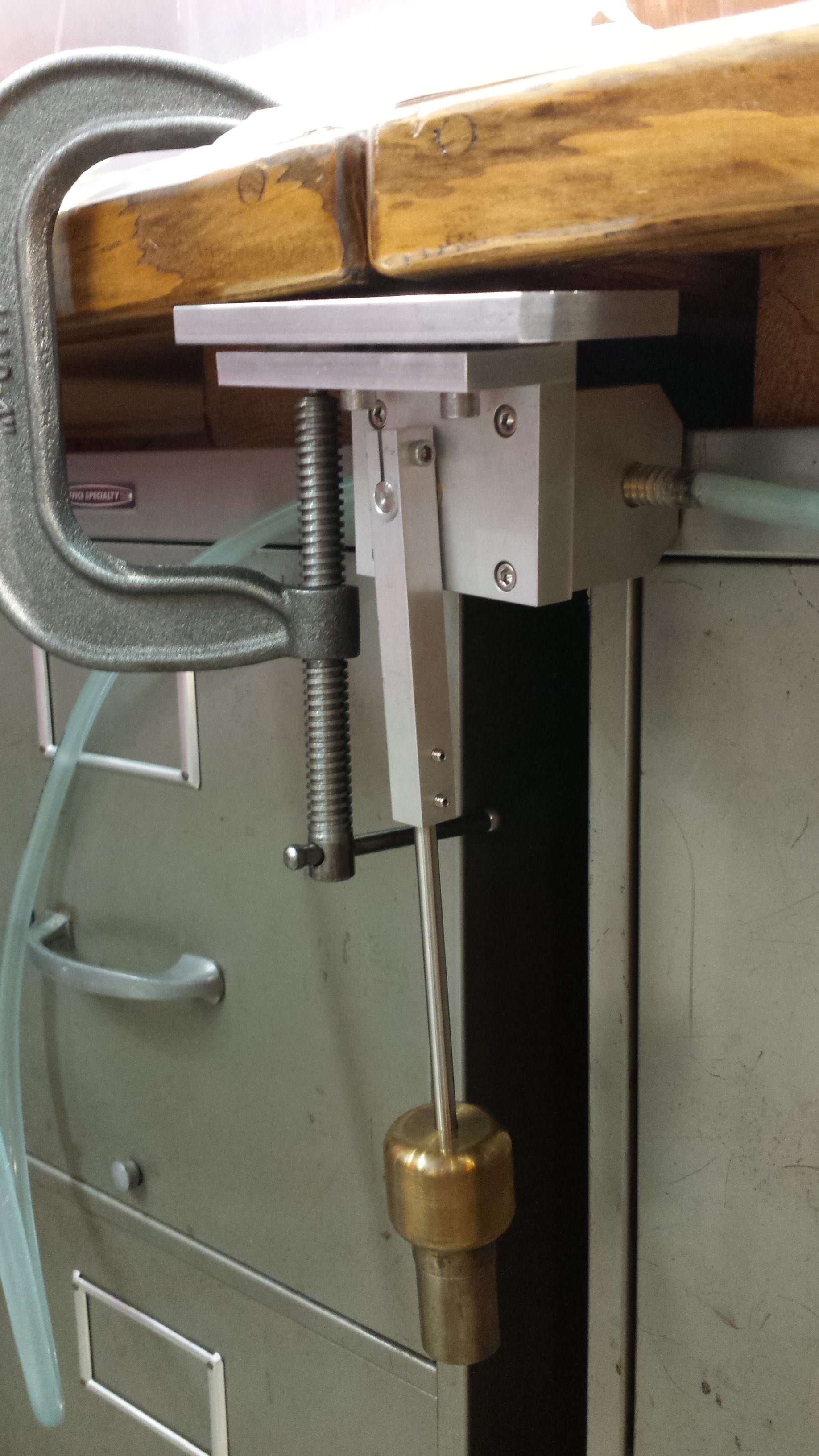
Place one of the small basins in the big water basin and the other basin
on the adjustable stand so that it is on a higher level. Then mount the
flow control under the table using a clamp (compare Fig. 4)
Fig.4 - Mechanical (manual) flow regulator lever.
Fill the big basin, including the small basin with water up to the edge of
the small basin. Fill the basin on the adjustable stand with water. Note,
that while floating the foil, the upper basin, has to be refilled several
times. Make sure to fill it up before the hose sucks air in. The upcoming
air bubbles can cause the carbon foil to rip apart!
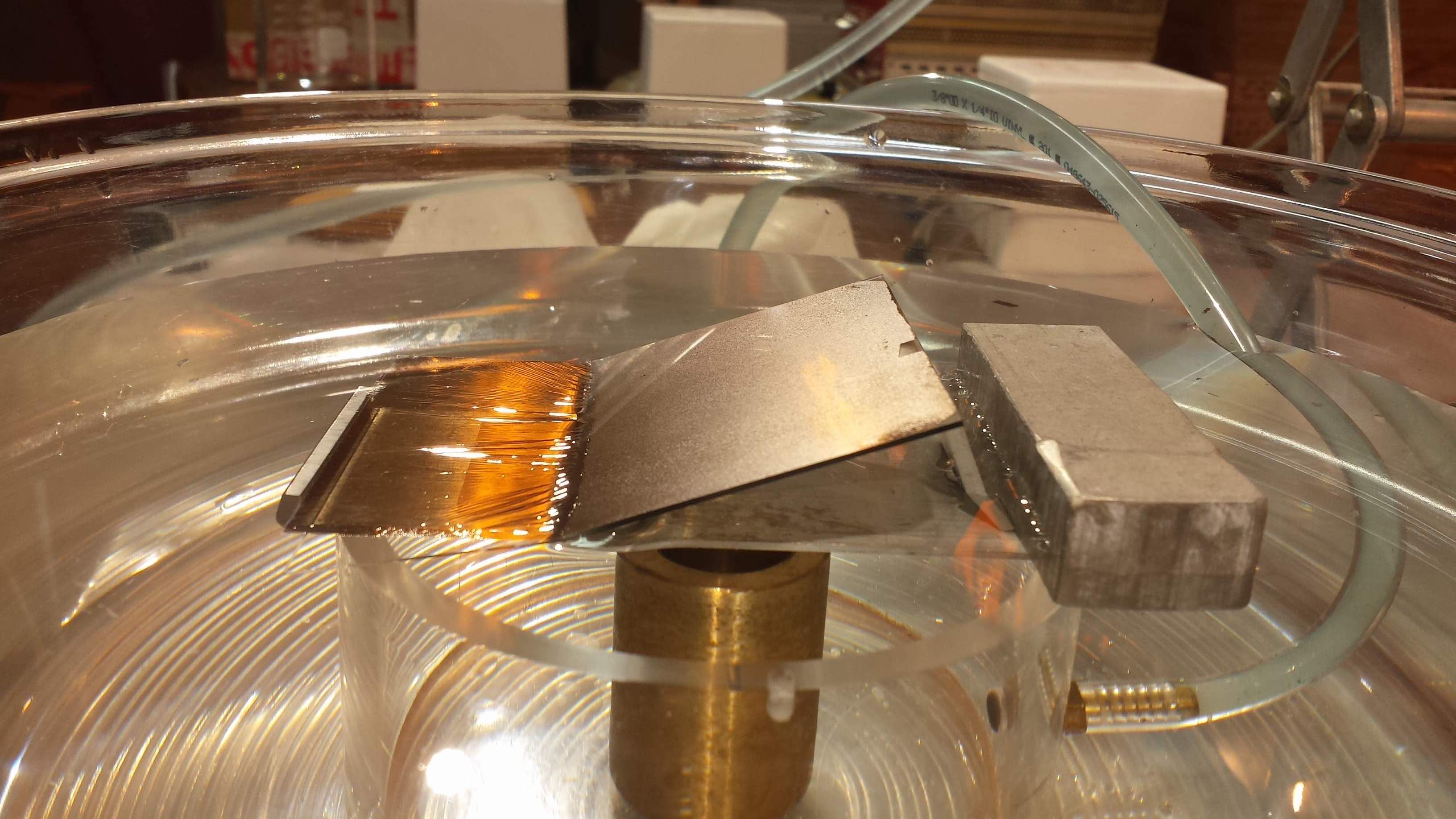
Place the plate across the small basin and place the elbow piece on the
plate. Support the elbow with the block (compare Fig. 5 (top))
Fig.5 - Different stages of the floating procedure.
Place the foil in a 45° angle on the elbow. Be careful and make sure to place the glass side on the elbow and the foil side up!
Have a razor blade and detergent ready. The blade (with a very thin coat of detergent on its tip) can be used to gently move the foil
(without touching it!) in a desired direction.
Make sure not to shake the table while the foil is in the water, again do not touch it, or breath on it!
Now you can start raising the water level very slowly ,so that the lower
edge of the foil barely touches the water level. This will be enough to start
detaching the foil. Give it some time and increase the water level further
(again, very SLOWLY!).
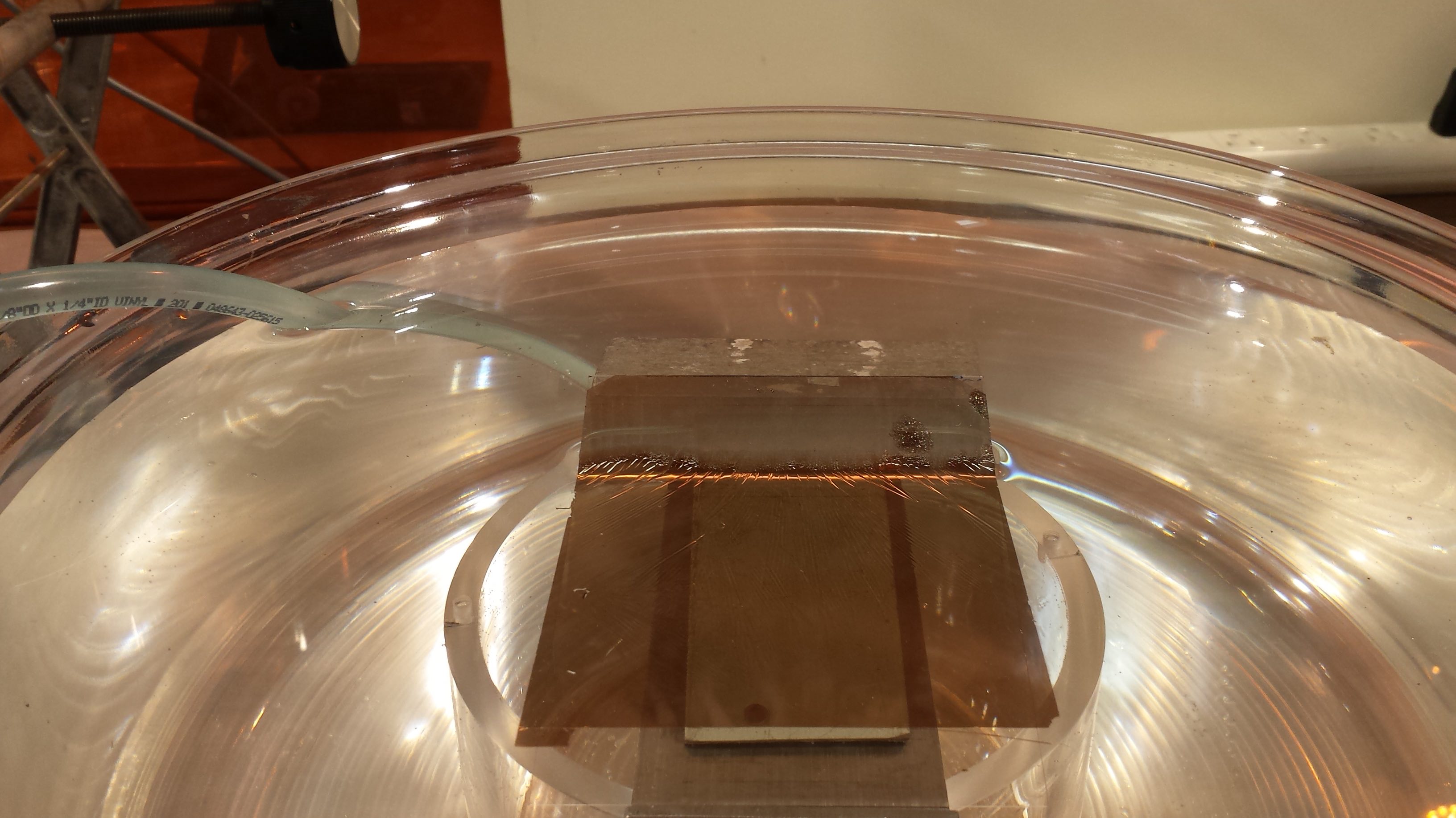
Watch out for pinholes, as the foil is likely to tear on
those spots. Sometimes the foil becomes lose on one side but is stuck on
the other. In that case, wait for several minutes. Eventually the foil will
come off (compare Fig. 5, bottom). If not, there is the option to slowly lower the
water level again and then raise the level again. However, be aware that
this procedure can cause the foil to fold itself up, which likely destroys it.
Fig.6 - Positioning of the MCP frame under the surface.
Fig.7 - DLC foil after catching it on a frame with mesh.
Once you managed to float the complete foil (usually takes up to 20 - 30 min, depending on quality of the foil and experience), it will float on the water surface (compare Fig. 5)
Catching foils on a frame
Once the foil floats on the water surface, you have to
carefully remove the glass plate, the elbow and the block from the basin, as you need space
to catch the foil.
Never make any sudden movements in the water.
The foil tends to be drawn in the direction of objects on the water surface, unless, they have detergent on it. This step is very critical, and you're most likely to destroy the foil now if you're not careful.
Hold the MCP frame with the latchable tweezers in one corner in one hand and hold the razor blade dipped in detergent in the other hand so you can
simultaneously direct the foil with it if required.
Very slowly bring the frame under the water surface (holding it 90° to the water surface, see Fig.6). You may need to "steer" the foil away, while doing this.
Then position the upper edge of the frame in a 90° angle underneath on edge of the foil.
Fig.8 - DLC foil ready for installation.
Slowly lift the frame (keep the 90° angle), while catching the foil. Once you caught it on the upper edge, it cannot go anywhere anymore and simply
move (slowly!) the frame all the way up and you should have the entire foil (hopefully intact) on the mesh (compare Fig. 7). Note that foils with
holes or tears on the outer part of the foil are still usable. Only holes in the middle of the foil, where one expects the beam spot are critical.
Start turning/rotating (very slowly, you do not want sudden air movements to destroy the surface!) the frame (along the edges) with the foil to remove the water.
After a few minutes, place the foil in a styrofoam casing (see Fig. 8), with one open side and let it dry for at least a day before you install it.
Installation
Make sure all voltages are off, and the MCPs are OUT of the beamline. Then follow the instructions to slowly vent the FSB (even if one foil is broken and needs to be replaced, the other might be intact)
and remove the flange on the East side of the FSB (which one depends on which MCP foil is being replaced).
Wear gloves when reaching inside the FSB. To remove the MCP foil holder some experimenters prefer to move the foil into the OUT positions, others find it easier when the MCP foil is in the IN position.
IN position is recommended here. The foil holder has two holes (one on the top right corner looking downstream, and one on the bottom left corner diagonally across from each other; see Fig.9 and 10) to attach the holder to the mirror assembly.
Grab the holder at the handle and slightly lift the frame up before sliding it off the 2 screws that hold the frame in position. Be careful with the hole assembly, you don't want to accidetally destroy fragile mirror wires.
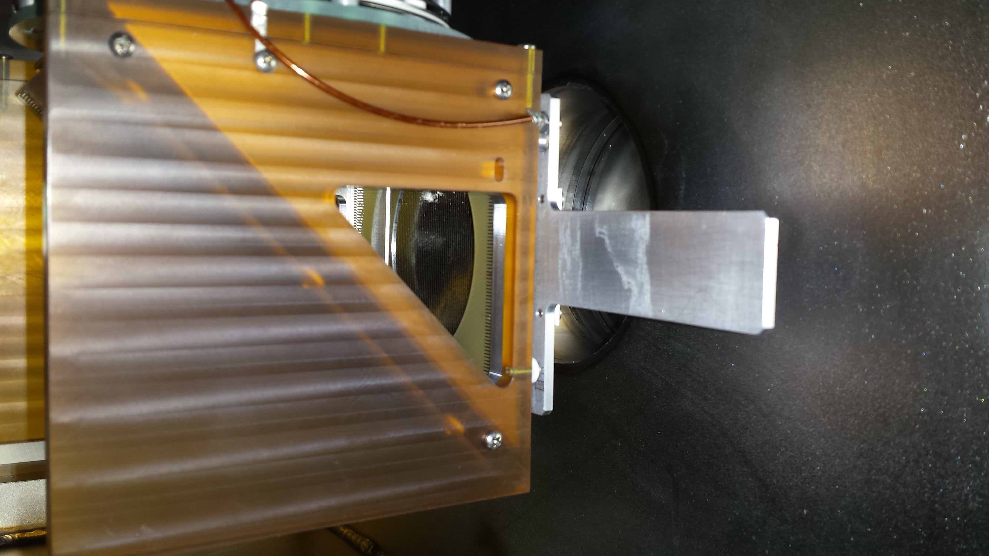
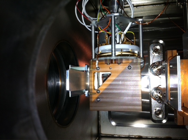
Fig.9 - MCP1 foil holder installed on mirror assembly.
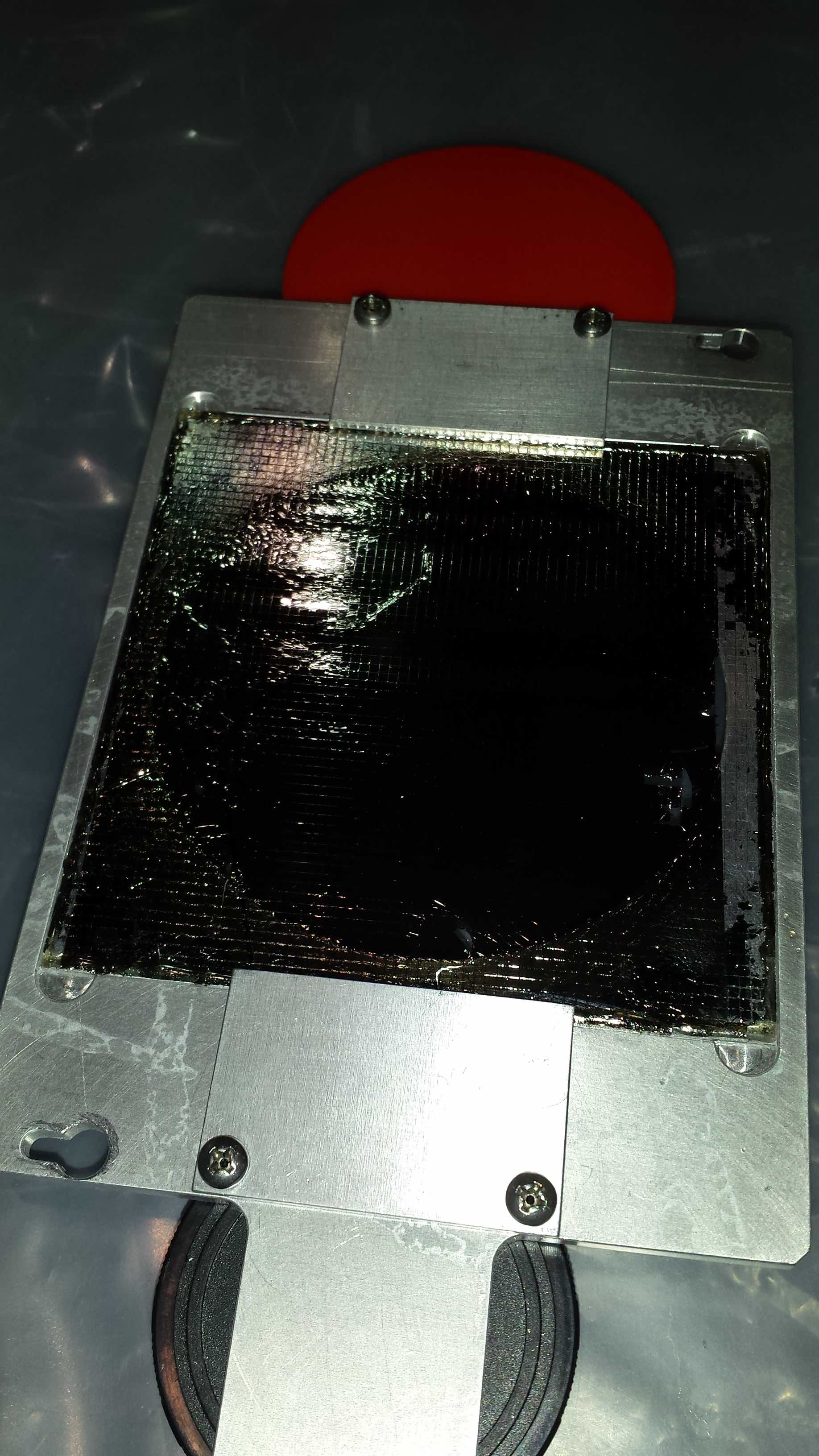
Fig.10 - MCP1 foil mounted on frame holder.
Fig.11 - MCP0 foil mounted on frame holder.
Fig.12 - MCP0 foil holder installed on mirror assembly.
Take the holder to a clean working surface, and detach the plates on either side, held by 2 phillips head screws each (see Fig.10).
Carefully lift up the MCP frame with a small screw driver (only touching the frame, not the mesh) at one of the 4 corners, and place the frame in one of the styrofoam boxes.
Install the new MCP frame (The side with the carbon foil needs to face upwards, otherwise you destroy it) by carefully placing it into the indent.
Reattach the plates. Now the holder + frame is ready to be installed again. Note, for MCP0 the holder has been designed differently (see Fig.11).
Slowly walk over to the FSB and reinstall the holder in the same orientation as before.
It's a bit tricky, as it's really hard to see the holes or the mounting points at the assembly. It's probably wise to practise this without a foil first.
Once the holder is in securely in place, clean the O-ring surface, inspect and clean the O-ring + groove and reattach the flange, move foils to OUT position and follow the procedure for slow pump-down.
It might take until the following day before the vaccum is good enough to start biasing the MCPs again.