Everything You wanted to know about the MCP but were afraid to ask
Final Slit Box pump down procedure with a thin foil.
Open EPICS "ED2 to SSD" or "ED2 to IC" Page - depending on which detecor is installed.
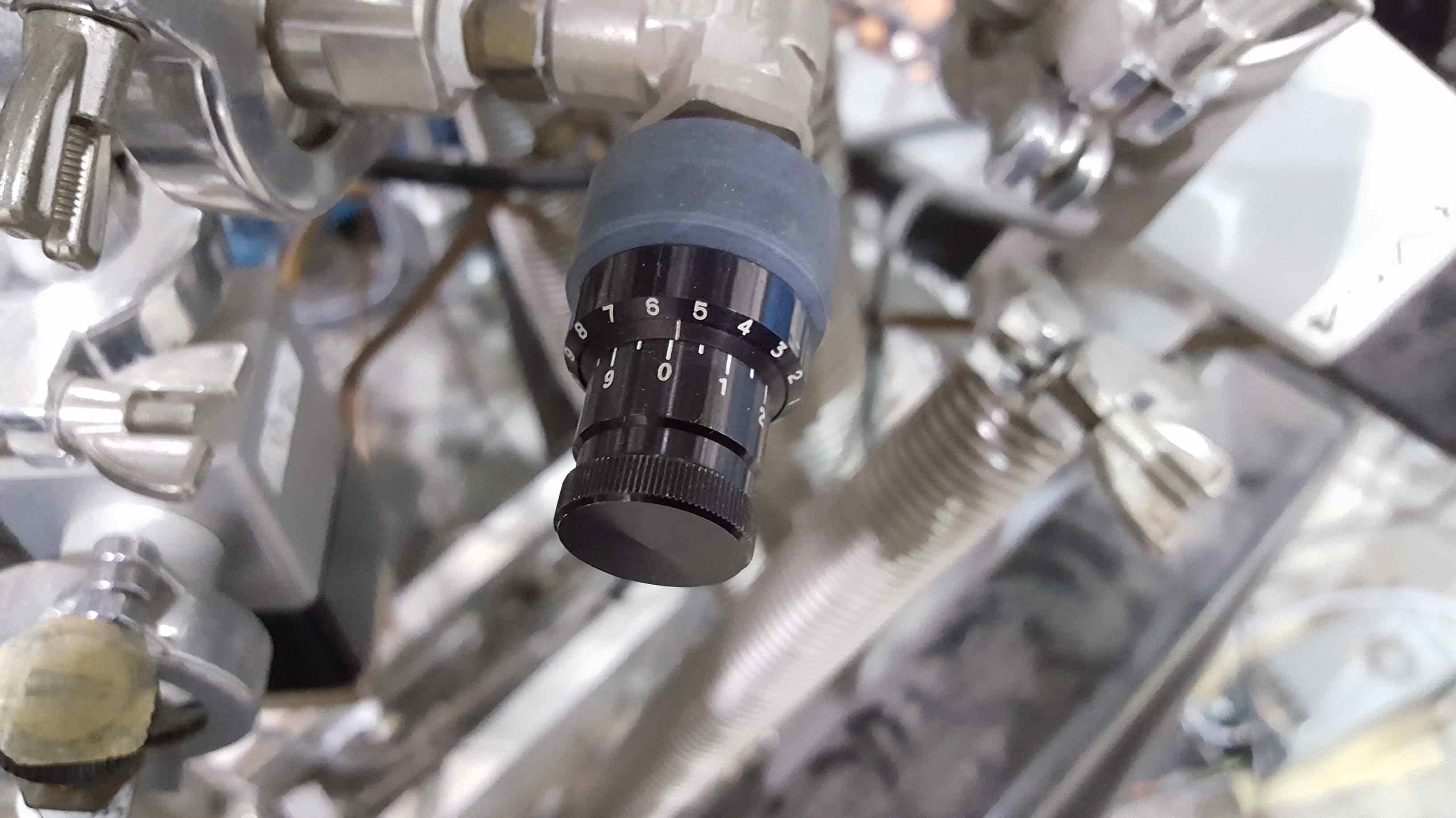
Turn the needle (manual) valve DRAMV74 (see Fig.1) located under the final slit box (West side) to max. 4.7.
Fig.1 Manual valve DRAMV74 under final slit box.
Ensure VV52 is closed.
Ensure, the MCP foils have been moved out of the beamline.
Turn on DRA:RP21.
Wait until pressure at DRA:CG21B is below 50 mTorr
Open DRA:RV54.
Watch Vacuum Gauges DRA:CG52 and DRA:CG52C to see that pressure drops by less than 1 Torr/second.
Ideally watch the rate on a laptop, while adjusting the needle valve if necessary.
To be extra careful, one can open RV54 with the needle valve closed, and slowly start opening it while watching the rate.
This avoids fast pressure drops that could potentially destroy the fragile foils. You may have to further adjust the valve during the pump down.
When Pressure drops to about 2 Torr on DRA:CG52, close DRA:RV54 and open DRA:RV52.
Turn on DRA:BP31.
Open DRA:PV31.
Close DRA:RV52.
Open DRA:BV52.
Turn on turbo pump DRA:TP52.
When pump starts up turn on DRA:IG52.
Final Slit Box venting procedure with a thin foil
Go to EPICS "ED2 to SSD" or "ED2 to IC" Page - depending on which detecor is installed.
Close DRA:BV52.
Turn off DRA:IG52 ion guage.
Turn off DRA:TP52 turbo pump and allow the pump to spin down, wait at least 30 minutes before venting with Nitrogen.
Otherwise, the pump could be damaged severely.
Ensure all the DRAGON vent valves are closed. DRA:VNT1 located on the "Differential Pumping" EPICS page should be checked. Other vent vales are labelled VV## where ## is the number.
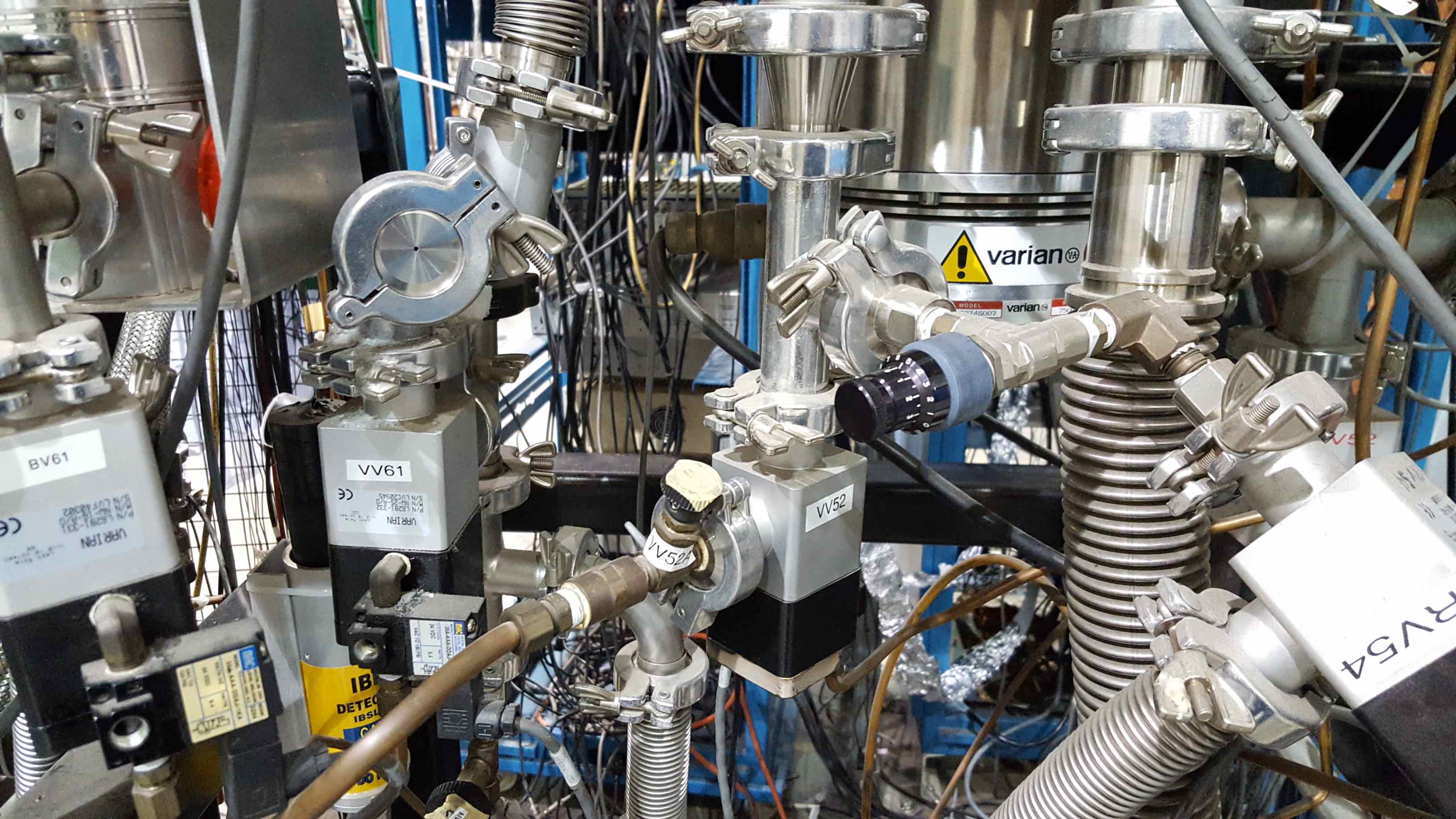
Ensure the manually adjustable vent valve (labelled "VV52A", see Fig.2) physically located near VV52 is only slightly open.
Fig.2 VV52A under final slit box.
Open the nitrogen gas cylinder located next to MD2, and activate the "dead man" 30 min time out switch.
Remember to reset the switch as the venting procedure will take at least an hour.
Open DRA:VV52.
Monitor pressure rise with DRA:CG52C and DRA:CG52 (ideally monitor the rate on a laptop while adjusting the manual valve VV52a), slowly open VV52a until the pressure in the final slit box starts to rise.
Close DRA:VV52 when DRA:CG52C and DRA:CG52 read atmosphere (760 Torr) or have saturated. The latter can happen at values below 760 Torr, when the gauge is slightly out of calibration
Close the Nitrogen gas cylinder.
Setup and voltages of the new MCP detectors.
With the upgrade of the DRAGON detector end station in 2008, DRAGON features two fast micro-channel plate (MCP) detectors with a timing resolution of typically 300 ps to 400 ps FWHM for an optimal non-destructive local time-of-flight measurement. The first detector is called MCP0 (previous MCP detector) at the upstream end of the final slit box.
MCP1 is larger and located at the downstream end at a distance of (59.0 +/- 0.5)cm from MCP0. The foils are now permanently attached to the MCP/mirror assemblies.
The MCPs are not mounted inside the beam pass directly. Instead they detect secondary electrons, which are emitted when the beam passes through thin carbon foils. The secondary electrons are then deflected into the MCPs by
setting wire planes to the required potentials. In order to maximize the flight path, MCP0 detects electrons from the downstream side of the foil whereas MCP1 is mounted backwards detecting the electrons from the upstream side
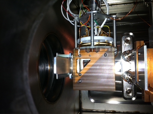
NOTE: DRA:MCP0 is upstream of the final slits (see Fig.3) and DRA:FCF, so it must be removed when tuning beam into DRA:FCF!
The detectors can be moved with the respective 'IN' and 'OUT' buttons on the 'DRAGON OPTICS (4)' page.
Fig.3 MCP0 power supplies for the base and the MCP detector.
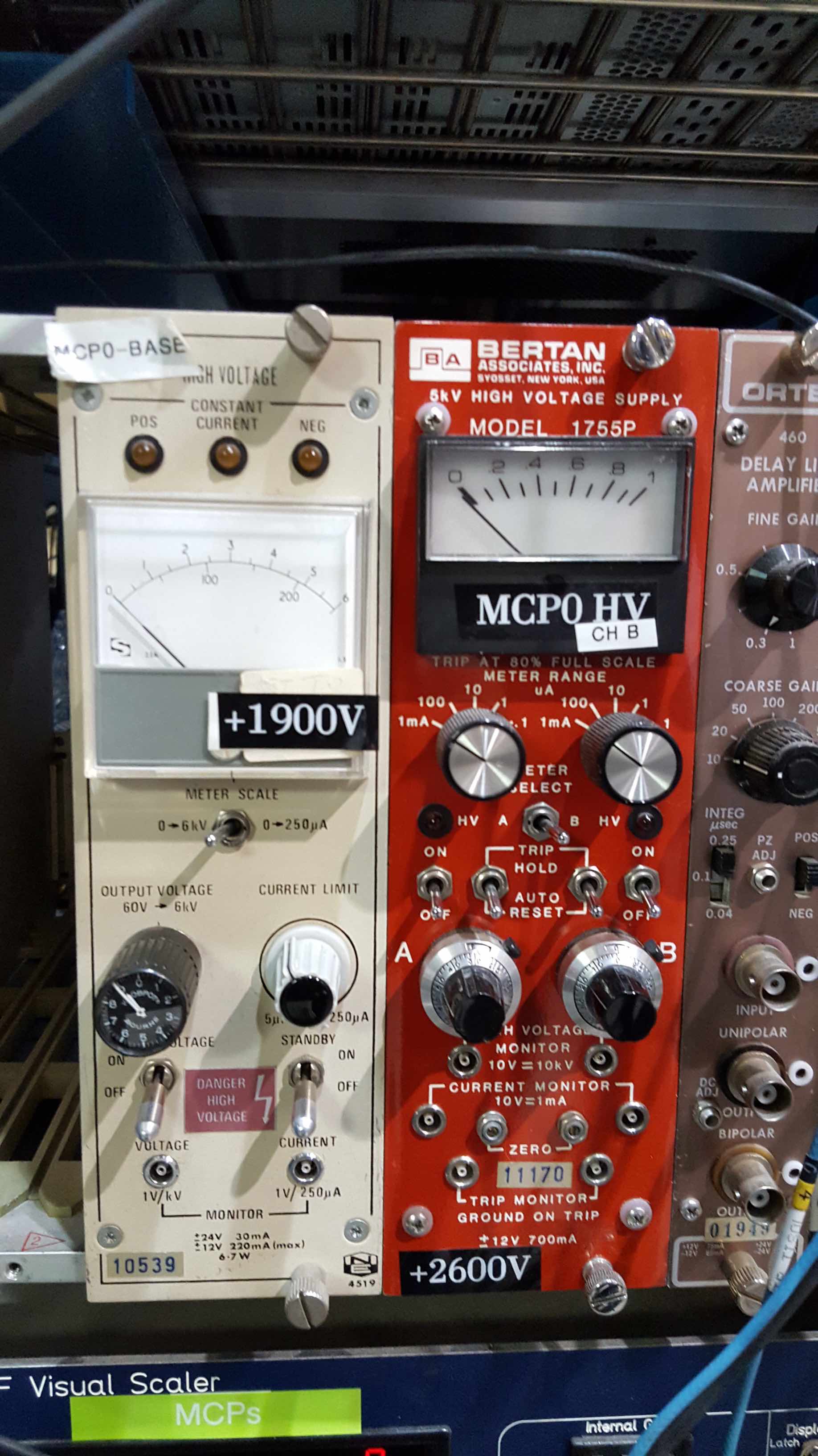
The MCP voltages are provided differently for the two detectors: MCP0 uses the Quantar voltage divider (on top of the FSB) and the bias is +2600 to +2800 V provided by the red Bertan +5 kV PWS (presently CH B, see Fig.4).
Fig.4 MCP0 power supplies for the base and the MCP detector.
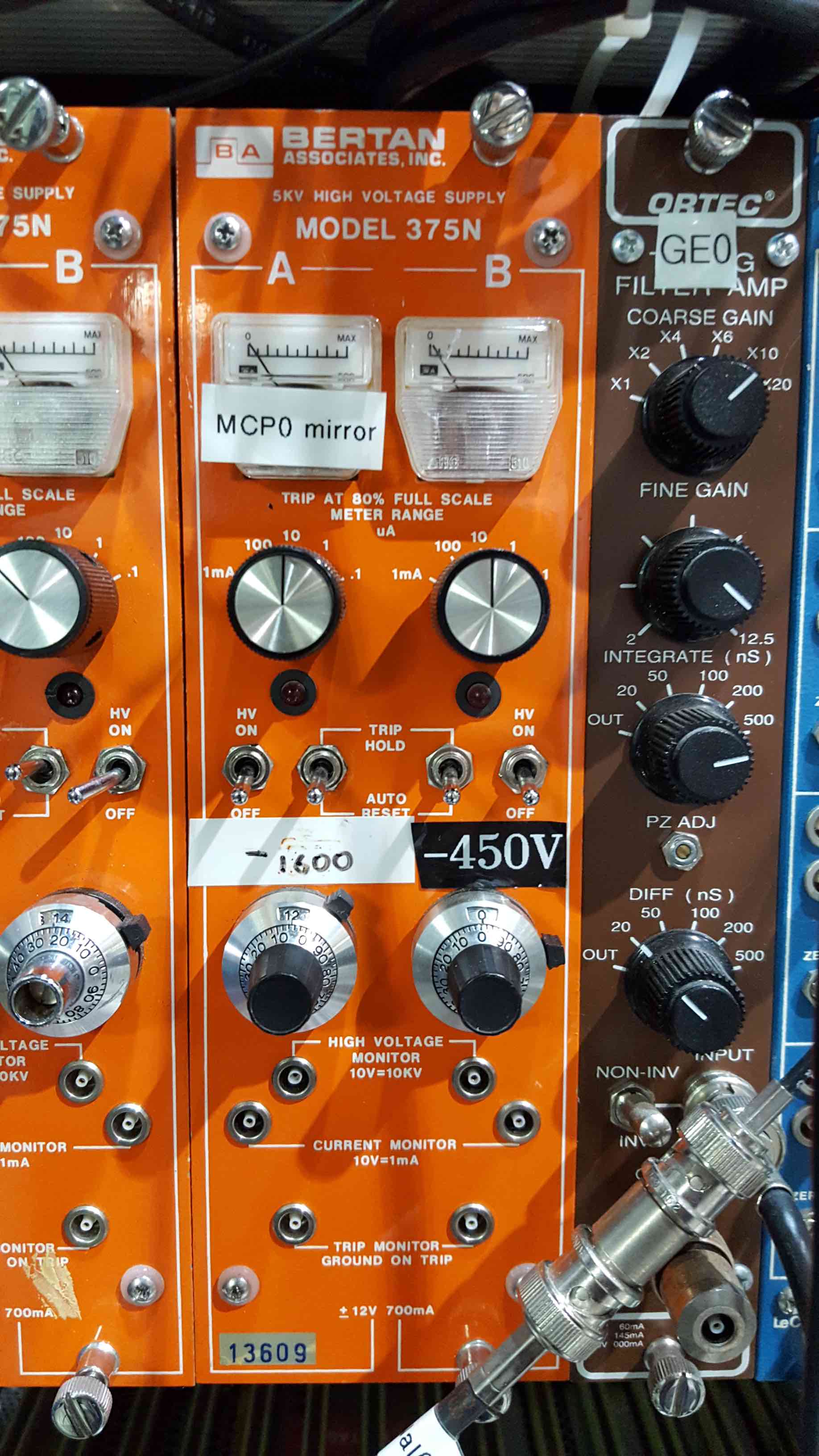
Voltages on the MCP0 base (+1900 V) and MCP0 mirror (-1600 V, orange -5kV Bertan PWS) are provided by separate power supplies (see Fig.4 and Fig. 5).
Fig.5 MCP0 power supplies for the base and the MCP detector.
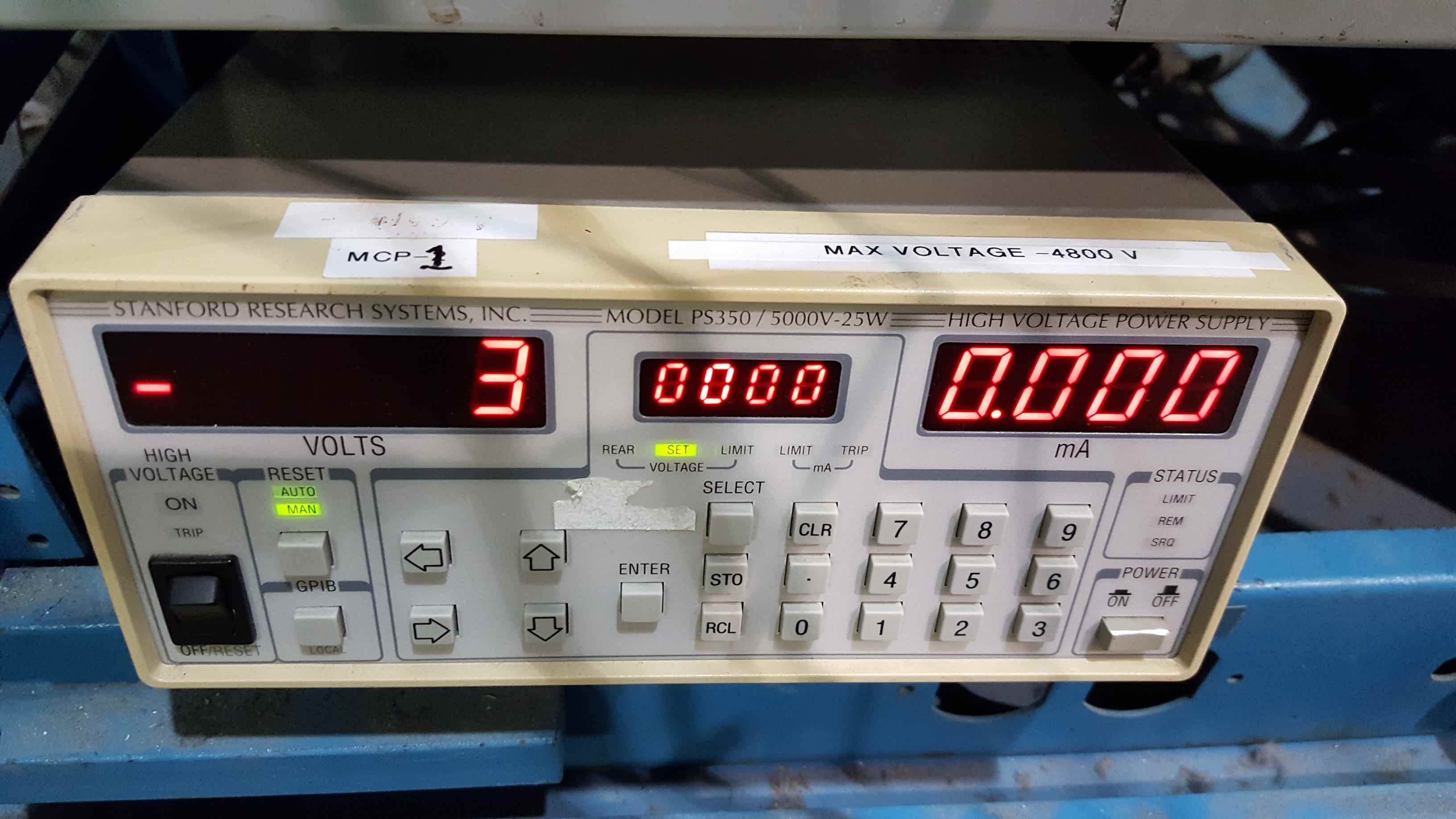
The MCP1 voltages (-4700 V) are provided by the +/-5 kV Standford Research PS350 (Fig.6) (polarity is set at the back of the PWS) and one common voltage divider (on top of the FSB).
Fig.6 MCP1 Stanford Research PWS.
Voltages should be ramped up slowly to protect the detectors. Always measure the voltage of the Bertan PWS with a fluke at the HV monitor (use crate as ground), while ramping up the voltage, as the scale on the dials may not be accurate.
Replacing the Electrostatic Mirror
Note: procedure has slightly changed since the upgrade.
If the mirror power supplies persistently trip on over-current (given that this feature is implemented), the
problem may be that one or more of the fine wires in the MCP mirror has
broken and is shorting that component of the mirror to ground or to an
opposite-polarity part of the mirror.
To check this, turn down ALL bias supplies to zero, disconnect the HV
cables where they connect to the vacuum feed-throughs (MCP plate on top of
the Mass slit box), and measure the resistance between each of the Pos and
Neg part of the mirror and ground and between Pos and Neg.
If any of these resistances is low, it is likely that a wire has broken.
It will be necessary to remove the MCP plus Mirror assembly to make a
closer examination.
Turn down bias voltages on MCP, mirror and other detectors
Bring both the MCP/Mirror and the Foil to the "Out" position
Isolate the Mass slit box from upstream and downstream parts of the vacuum system.
Follow the venting procedure for a slit box with a thin foil (above), using a manual valve to
ensure that the initial rate of venting N2 is low (less than 1 Torr/second after the turbo pump has spun down)
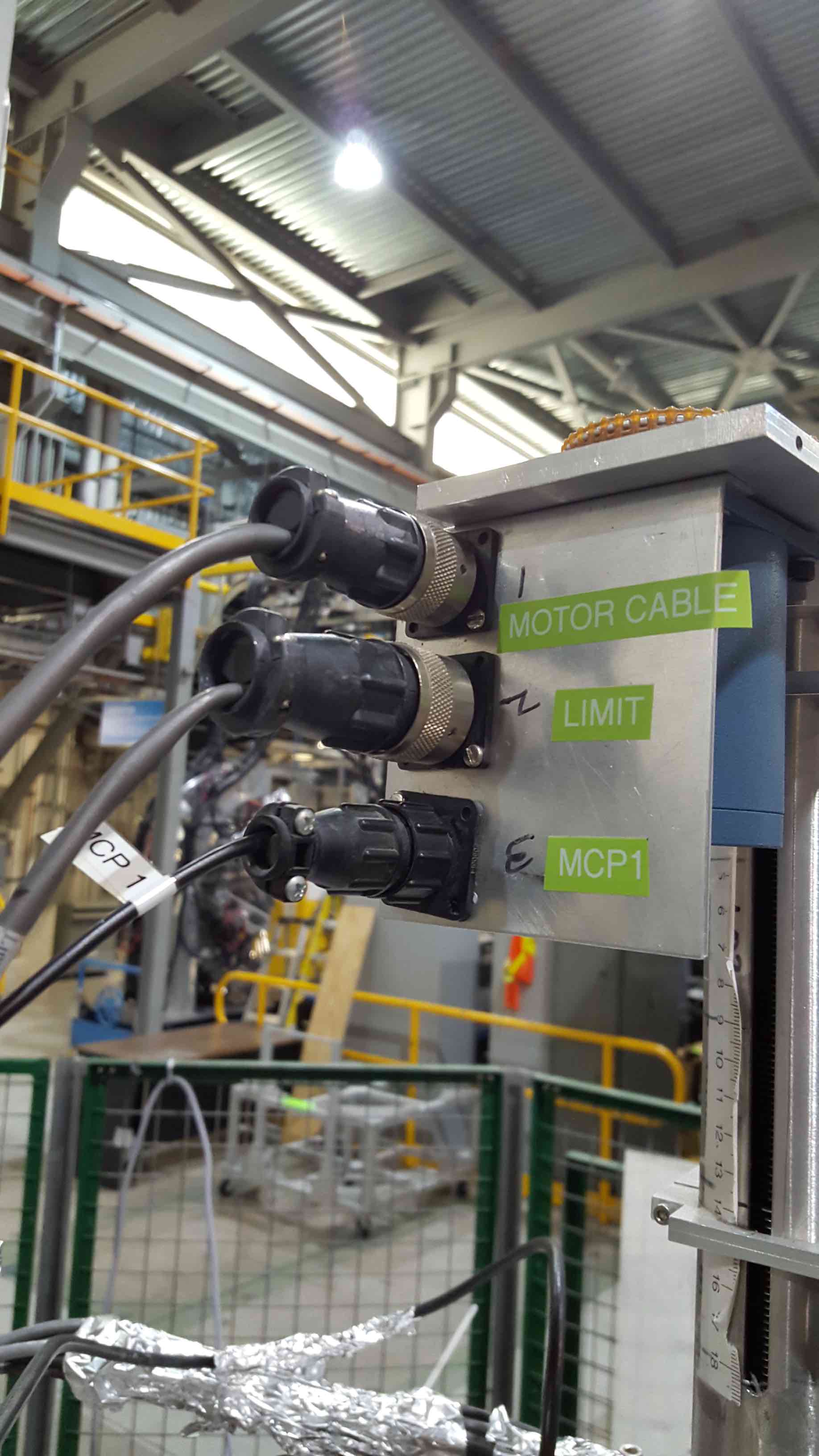
Disconnect the EPICS control cables of MCP/Mirror (see Fig.7)
Fig.7 MCP motor epics control cables.
If radioactive been has been delivered, follow procedures for checking for possible contamination (Work permit and RPG approval required!) of the assembly (DO NOT make a swipe test of the wires!)
To swipe the final slit box, it's easiest to remove the flange on the East side, and swipe the valve downstream of MCP1.
Once, you have approval to open the FSB and swipes turned out negative, clean the top of the FSB, to prevent dust and random objects to fall into the FSB.
Then, unbolt the top flange the MCP/Mirror assembly is attached to, and remove the whole assembly very carefully. It's advisable to remove the MCP foil and storing it in a safe place before lifting out the assembly.
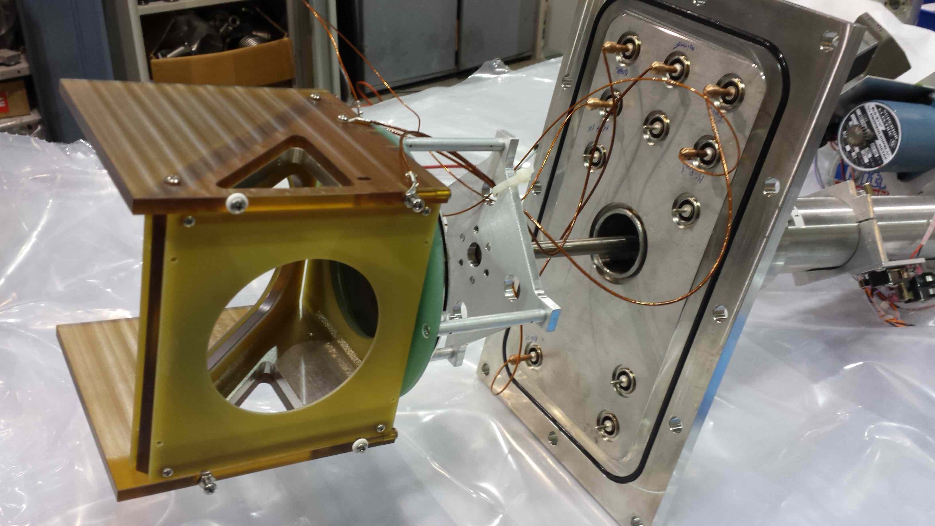
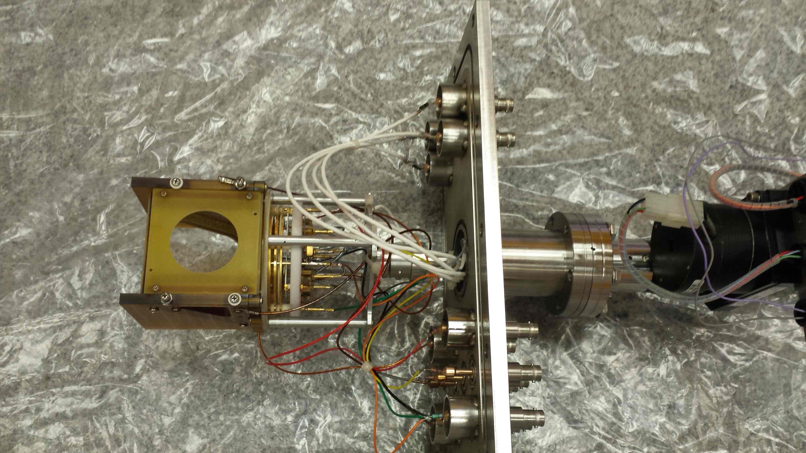
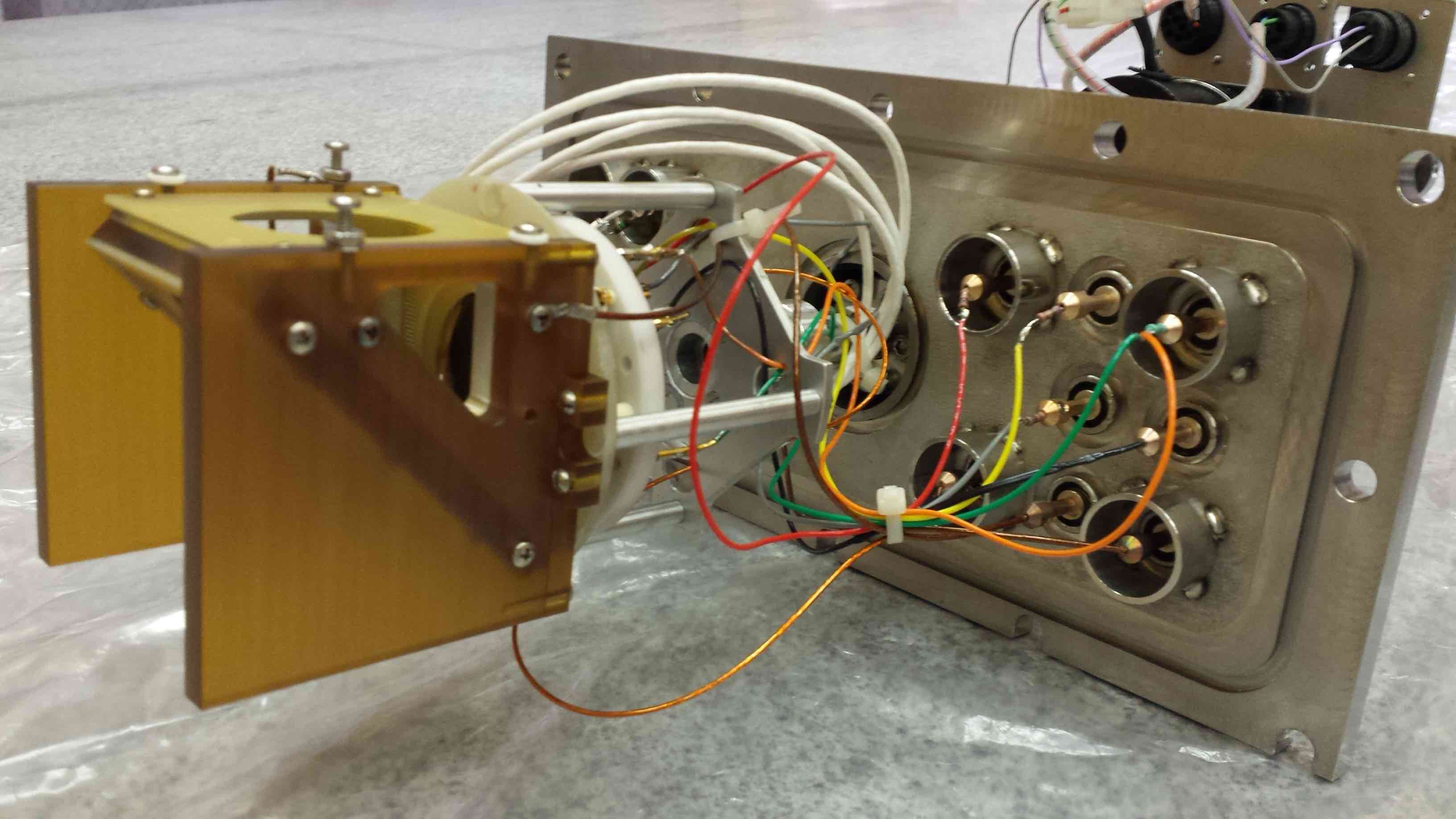
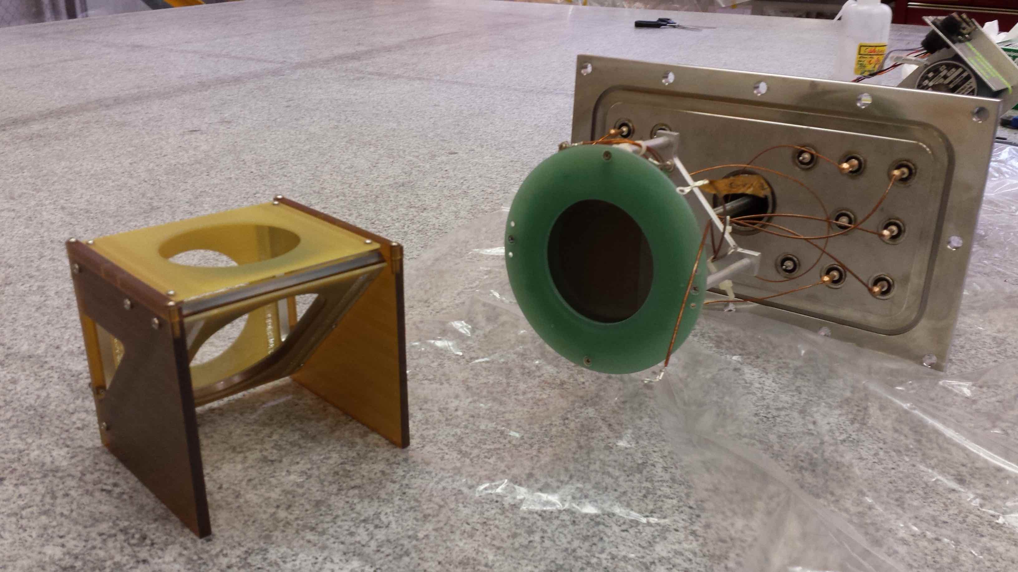
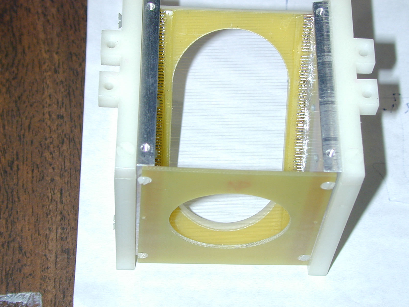
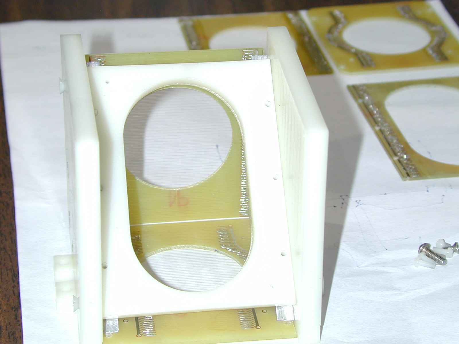
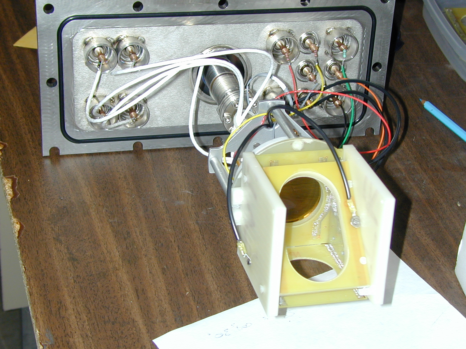
Move the assembly to a clean work area and look for broken wires and other defects. The MCP1 assembly is shown in Fig.8 and the MCP0 assembly in Fig.9 and Fig.10.
Fig.8 MCP1 mirror/MCP assembly.
Fig.9 MCP0 mirror/MCP assembly.
Fig.10 MCP0 mirror/MCP assembly.
If mirror wires are broken, the plane(s) must be replaced by spare
plane(s). Look for them in the DRAGON cabinet that contains parts for the end detectors.
Disconnect the bias voltage leads for mirror, foil and base from the mirror assembly, that are held in place via ring terminals and screws.
Try hard not to lose the tiny screws, nor to drop them on a wire plane!
Make note of which lead is connected to which plane.
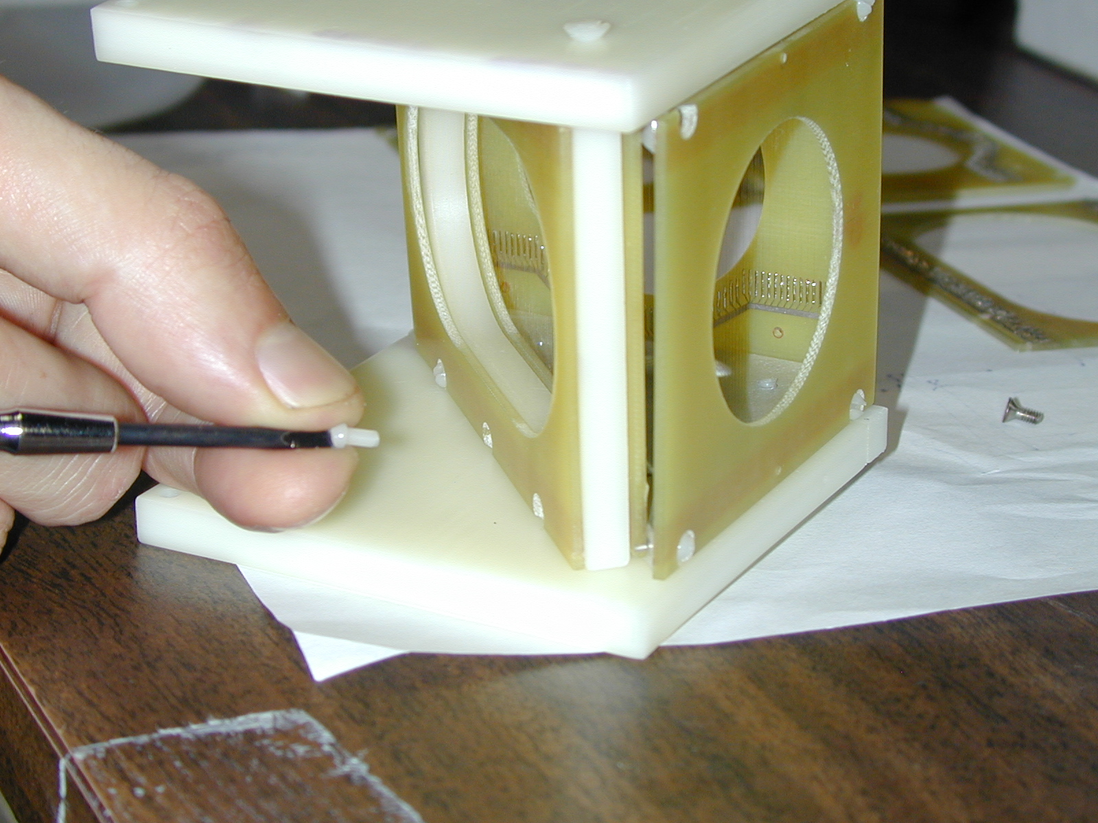
Detach the mirror assembly from the insulating ring (4 nylon screws), see Fig. 11.
Note the orientation of the insulating box with respect to the upstream direction.
Fig.11 MCP1 mirror detached from insulating ring.
Remove wire planes as necessary, undoing the tiny nylon screws.
Orient the assembly to minimize the odds of a screw falling onto wires.
Note which sides of the G-10 boards the wires are on, to get it the same
upon re-assembly.
Mount the replacement planes. Note that the corner where two planes
meet at right angles does not have a permanent internal spacer to define
the separation of the two side plates: before tightening the mounting
screws at this edge, verify that the side plates are parallel to each
other. Check that the wires are still under tension.
Remount the mirror on the insulating ring. (If side-plates aren't
parallel, the holes in the attachment lugs may not match the holes in the
insulating ring.)
Re-attach the bias voltage leads
Measure resistances between Pos feedthrough or Neg feedthrough and
ground, and between Pos and Neg feedthroughs.
If resistances are low, look for possible causes. (Pray that no wires
were broken during the re-assembly process.)
If resistances are high, remount the assembly on the final slit box,
restore EPICS cables, pump down slowly (hand valve to control initial
rate).
Have the Detector Facility expert replace the broken wires to ensure that we have spares for the next replacement.
Some of the stages of the mirror replacement for an older version of the mirror assembly are shown in the images below.
Chris Ruiz and Dave Hutcheon
October 13, 2005
Updated by Annika Lennarz
January 25, 2019
MCP/Ion Chamber Voltage Trip Alarm System Note: this feature is not implemented yet since the upgrade.
For background information, see the section on the ion chamber HV trip alarm, located here.
The purpose of this alarm is to alert the operator (you) to a malfunction of the MCP. We are operating under the assumption that the voltage trips due to a wire in one mirror grid breaking and shorting to the other grid, such that monitoring only one of the voltages is sufficient.
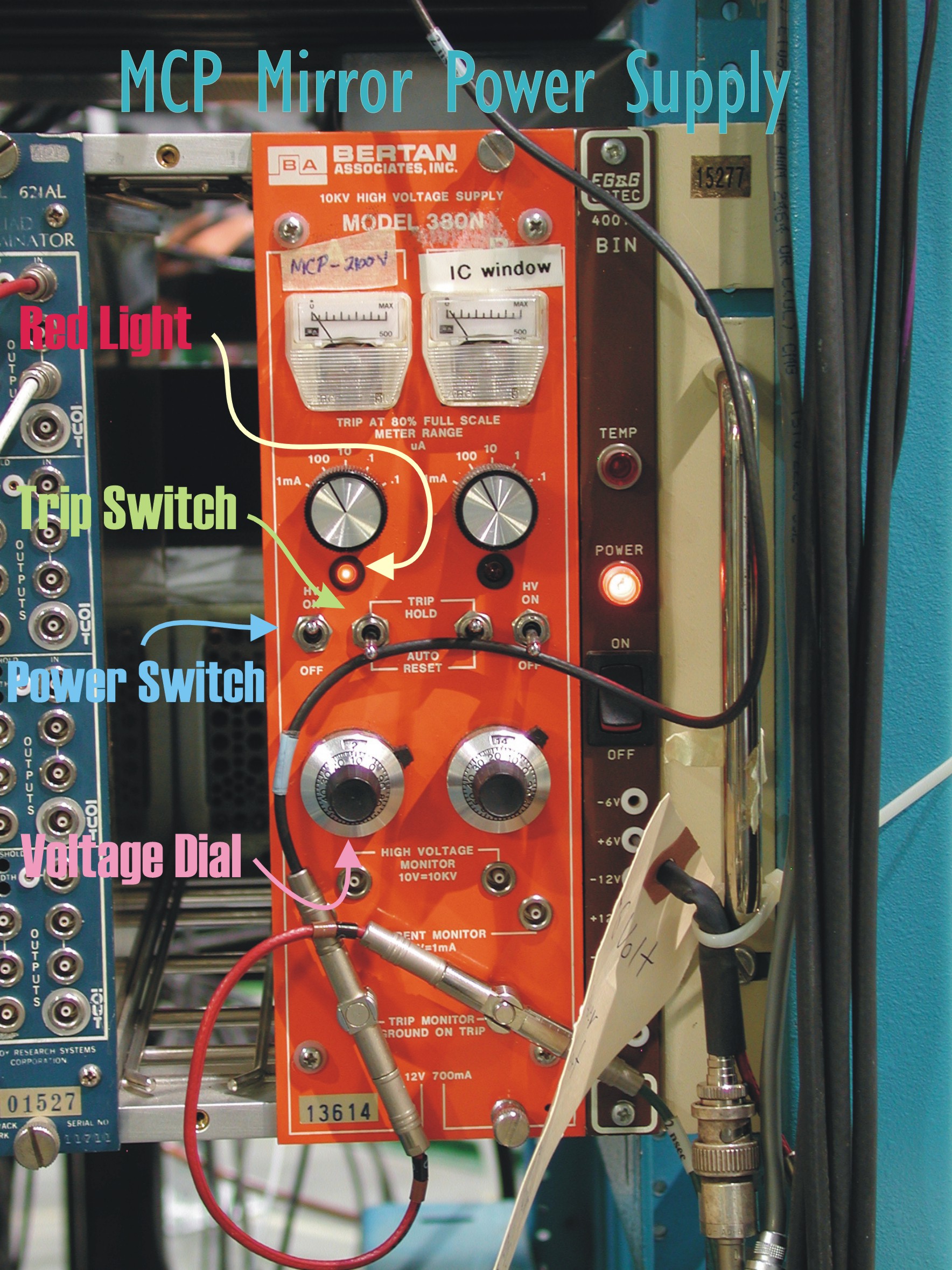
The electrostatic mirror grids are biased to +-2100 V. The negative bias is supplied by a Bertan supply. This supply has a feature which allows communication of a voltage trip (i.e. the power supply shuts itself off because it is drawing too much current).
This signal is "daisy-chained" with similar signals coming from the ion chamber supplies, and causes an alarm to go off in the counting room.
If you hear this alarm:
Pause the run
Go down to MCP negative mirror power suply in the DRAGON area
Turn left-hand power switch off
Set voltage dial to 0
Turn power switch back on
Flip the trip switch down to reset and then back up again to trip hold mode
Red light should have turned back on
Slowly turn voltage dial back up
Ensure red light is on. If not, repeat steps 2-6
Resume the run
If this still does not solve the problem, then the following steps must be taken:
Turn off all MCP voltages
Once voltages are off, remove cover from viewport on focal plane chamber and visually inspect MCP apparatus
If everything is intact, reattach the viewport cover and reapply the voltages. *NOTE* The "tripped" power supply will have to be set to zero and its power recycled before it can be turned back on.