


|
 |
Operating
Double-Sided Silicon Strip Detectors (DSSSD)
Overview
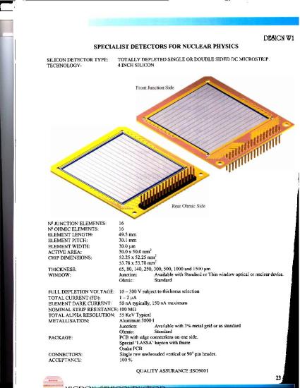
The DSSSD's are purchased from Micron Semiconductor
(www.micronsemiconductor.co.uk). They consist of 16 strips on the
junction side and 16 orthogonal strips on the ohmic side, element pitch
being 30.1 mm for a total coverage of 49.5mm x 49.5mm. They are mounted
on a PCB board, with 34 pins on one edge. The middle pins of the two rows
are ground and bias voltage, the other pins signals from the 32 strips.
They are connected via 34-conductor flat cable to a vacuum feed-through,
from which another flat cable leads to the pre-amp box. From the pre-amps
the "front" signals and "back" signals are conducted by separate flat
cables to amplifier/discriminators, whose output goes to ADC's and the
DRAGON trigger logic.
There are two types of DSSSD currently in use from Micron. They are the typical 'old style' Micron W1 model, usually 300 um thickness with 0.34um Silicon equivalent deadlayer.
In addition, there is the more modern W1(G) or "Tengblad" design, which has a grid metalization over a small percentage of the stop area that allows a thinner (0.1um silicon equivalent)
deadlayer over most of the strip area. DRAGON DSSSD detectors are stored in the "Detectors" cupboard in the DRAGON experimental area, and a logbook inside lists the detectors and their status.
Whenever a detector is removed from the beam-line and put back into the cupboard, an entry should be made in the logbook detailing what conditions it was exposed to.
CAUTION
The DSSSD's are expensive, non-robust items. Some things not to do:
- Break the very fine wires which connect the strips to the traces on
the PCB board.
- Bombard them at high rates with heavy ions. For DRAGON, practically
speaking, this means don't put beam on a DSSSD unless it has been reduced
to < 1000 Hz by beam attenuators between the ion source and RFQ.
Mounting and Electrical Connections
Attention: each of the 32 strips is connected by a very fine wire to
its trace on the PCB (see picture, above). Before mounting or
demounting a DSSSD, find these wires so you know where not to put your
fingers.
- If the detector mount was in use and cooled, it must first be warmed
up,
to avoid condensation (and subsequent slow pump-down). Change the
refrigerator setpoint to +20c, let it come up to that temperature, and
run for another 10 minutes before stopping the fridge. Disconnect the
cooling lines, not right at the top plate but 20cm away from the end.
(This connection will/should be hidden under electrical tape at a break
in the foam rubber insulation.)
Close valve IV61 to isolate the End detector box from the Final slit
box. Vent the End detector box through the Ionization Chamber valve
system.
-
Disconnect the ribbon cable at the lid end (not the pre-amp box end),
undo the bolts which secure the lid. Lift the lid and remove it, being
careful not to bang the detector mounting on the way up. Carry it over
to a clean bench area and set the lid down so that the DSSSD is facing
up (tilted). (A spacer under the mounting plate will help prevent
rocking.)
-
Disconnect the ribbon cable from the DSSSD (firm pull). Find a small
screwdriver, suitable for the small screws on the retaining bars around
3 sides of the DSSSD board, and a small container to put the screws in.
Note where the fine wires are! Remove the screws from the
side bars (running parallel to the strips), taking care not to let the
bars slip, and remove the bars. While your Assistant holds the DSSSD
down on its locating pins, remove the lower retaining bar. Raise the
DSSSD directly upward away from the cooling plate (so as not to damage
the fine wires on the underside) and slide the pins out through the slot
in the cooling ring.
- Mount the new DSSSD. Grip it so that the visible strips run at
right angles to the edge with the pins, and you are holding it by the
edges. The two holes in the PCB closest to the readout pins should be
lowered onto the two locating pins on the cooling plate. Press down so
that the locating pins keep the DSSSD in the right position while the
bottom retaining bar is screwed in place. Re-mount the side retaining
bars.
- Re-mount the lid on the End detector box, put in the 4 screws and
re-connect the ribbon cable. If you are unsure about the orientation of
the ribbon cable (because the keys have been removed!), observe the
leakage current when a few volts are put on the DSSSD bias supply: the
correct orientation should have much lower leakage current.
Pump down the End detector box. If the Mass slit box is still at
high vacuum, consult an expert on how to bypass interlocks so as to open
IV61 after the End box has been roughed out.
- If the cooler is to be used, reconnect the coolant lines, start the
refrigerator and check for leaks at the connectors. When no leaks,
re-cover with foam rubber and set the refrigerator for -15c.
- Make a note in the Hardware logbook, giving the i.d. of the new
detector (and of the old one, if one was removed).
Check-out with Sources
Using the FSB calibration source
|