Ionization chambers and DSSSDs have their own strengths and weaknesses.
An ionization chamber has relatively poor resolution compared to the DSSSD but compensates for this with the ability to discriminate
recoils from isobaric contaminants by their energy loss signal. A DSSSD has
superior energy resolution, timing capabilities, and produces a strong E signal
but is often unable to separate isobars which are very close together in kinetic
energy. The Hybrid detector will consist of an ionization chamber set in front
of a DSSSD along the beam axis to act as a superior ΔE-E end detector that
can discriminate isobaric contaminants from the beam particles and from the
recoils while preserving high resolution and fast timing capabilities.
Installing a DSSSD in the hybrid detector
When not in use, the hybrid IC is stored in the IC vacuum chamber at the DRAGON end detector station.
When the chamber is under vacuum, follow the slow venting procedure for the IC.
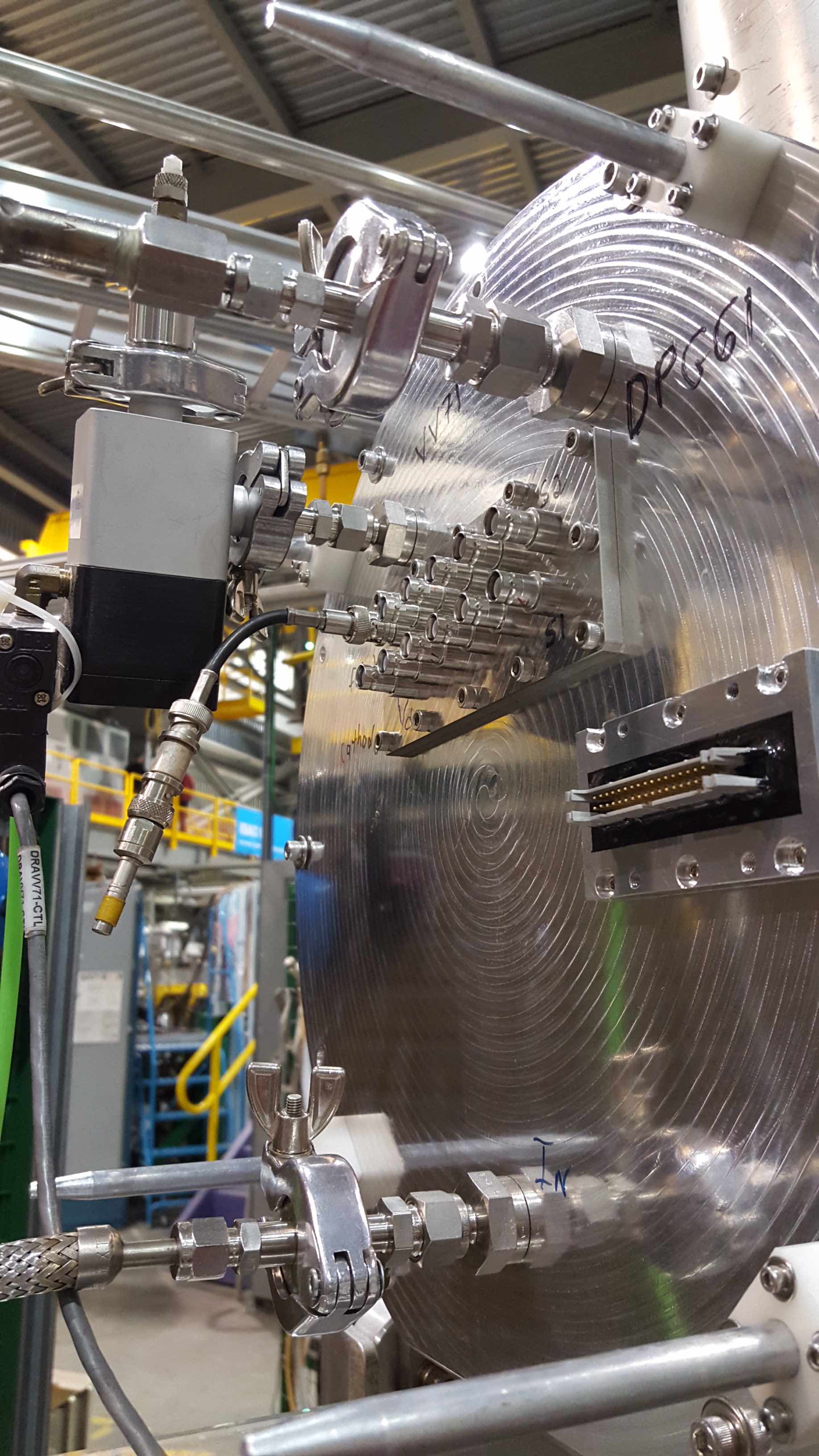
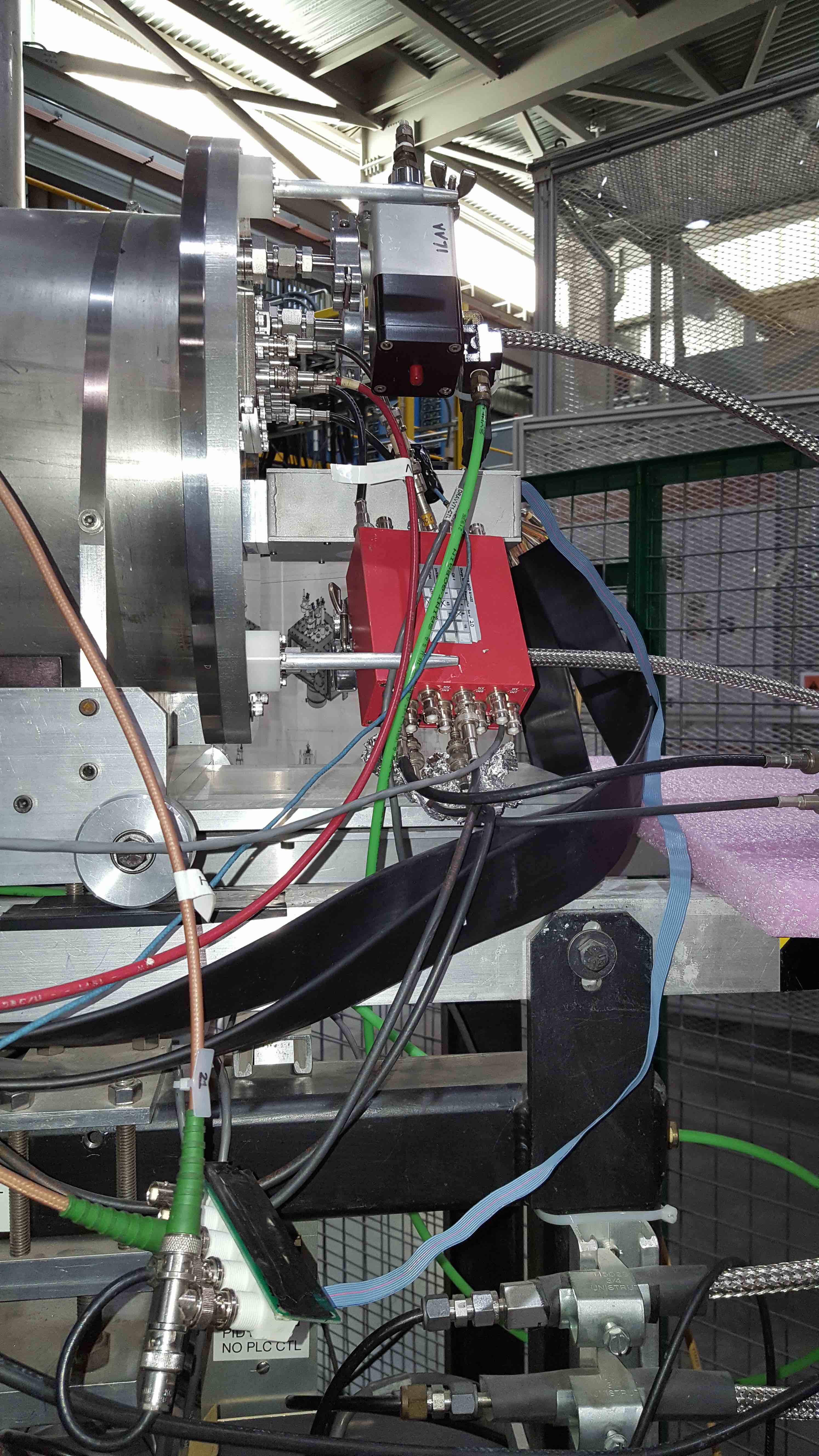
Once the chamber is on atm. remove the vent valve VV71, gas inlet and outlet hoses from the back of the IC flange (compare Fig.1), and possibly the electronics if attached.
Fig.1 - IC flange with gas inlet and outlet, VV71 and signal ouput feedthroughs for IC and DSSSD.
Remove the bolts.
Have a large, clean working surface ready before removing the flange by sliding it off the four rails that support the flange.
It's advisable to have two people for this. Make sure to support the flange while removing it, you don't want the IC to "bump" into any objects.
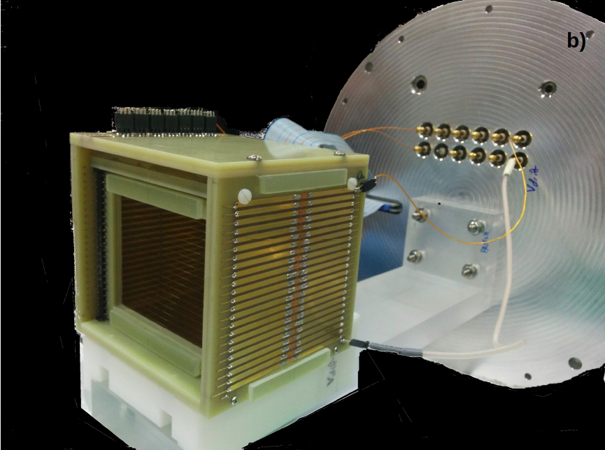
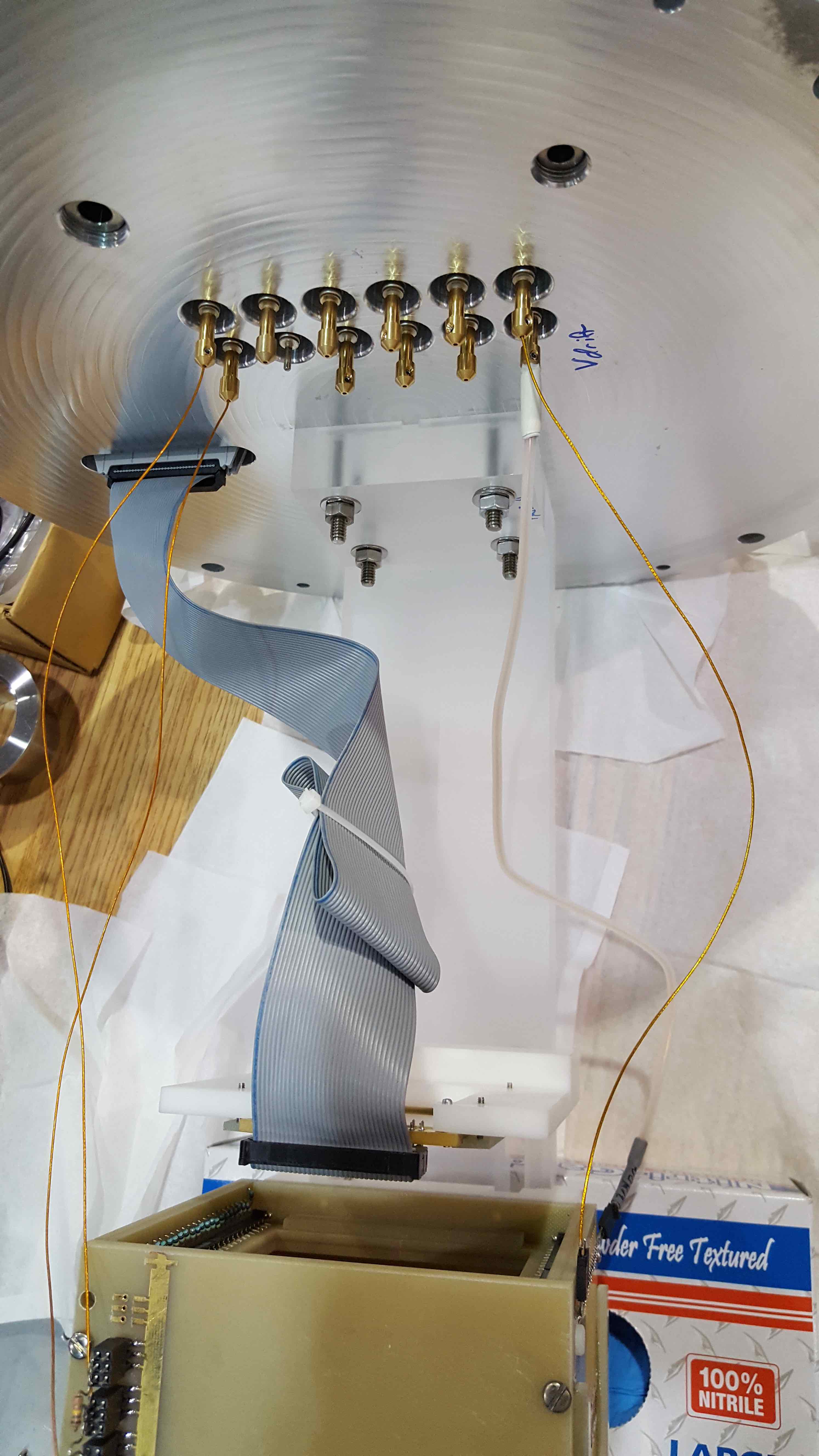
Take the flange + hybrid assembly to your working surface and support the IC (Fig. 2).
Fig.2 - Hybrid IC with DSSSD installed and connected.
The DSSSD holder is attached downstream of the IC with 2 bolts at the bottom. A bracket attached with 4 screws holds the DSSSD in place (See Fig.3).
Carefully mount the DSSSD on its holder and secure it with the bracket. Then mount the DSSSD downstream of the IC. Do not put it too close to the chamber, 11mm is recommended.
In any case, take note of the exact distance between DSSSD and IC.
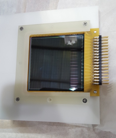
Fig.3 - DSSSD mounted on holder.
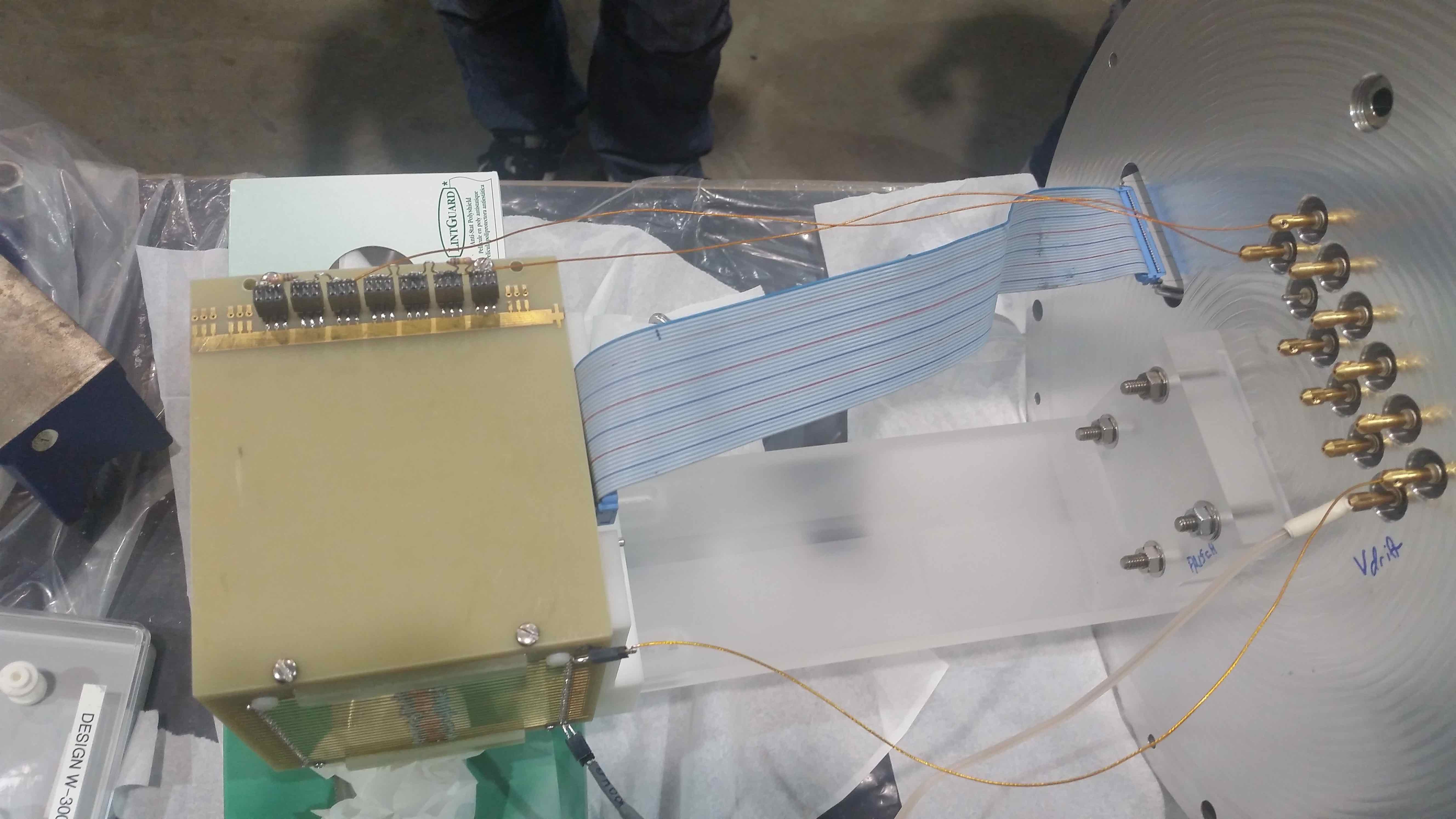
Connect the ribbon cable to the DSSSD connector. Pay attention to the orientation of the DSSSD pin connector.
In the example in Fig.4, the ribbon cable needs to be twisted to match the orientation of the pins.
Fig.4 - Hybrid with twisted ribbon cable.
Test feedthrough connections before installing the hybrid.
Carefully re-install the hybrid (2 people is recommended) and tighten the flange (criss-cross pattern).
Re-attach the vent valve and gas inlet/outlet.
Operate the hybrid detector
Attach the DSSSD preamp box. See instructions for DSSSD operation.
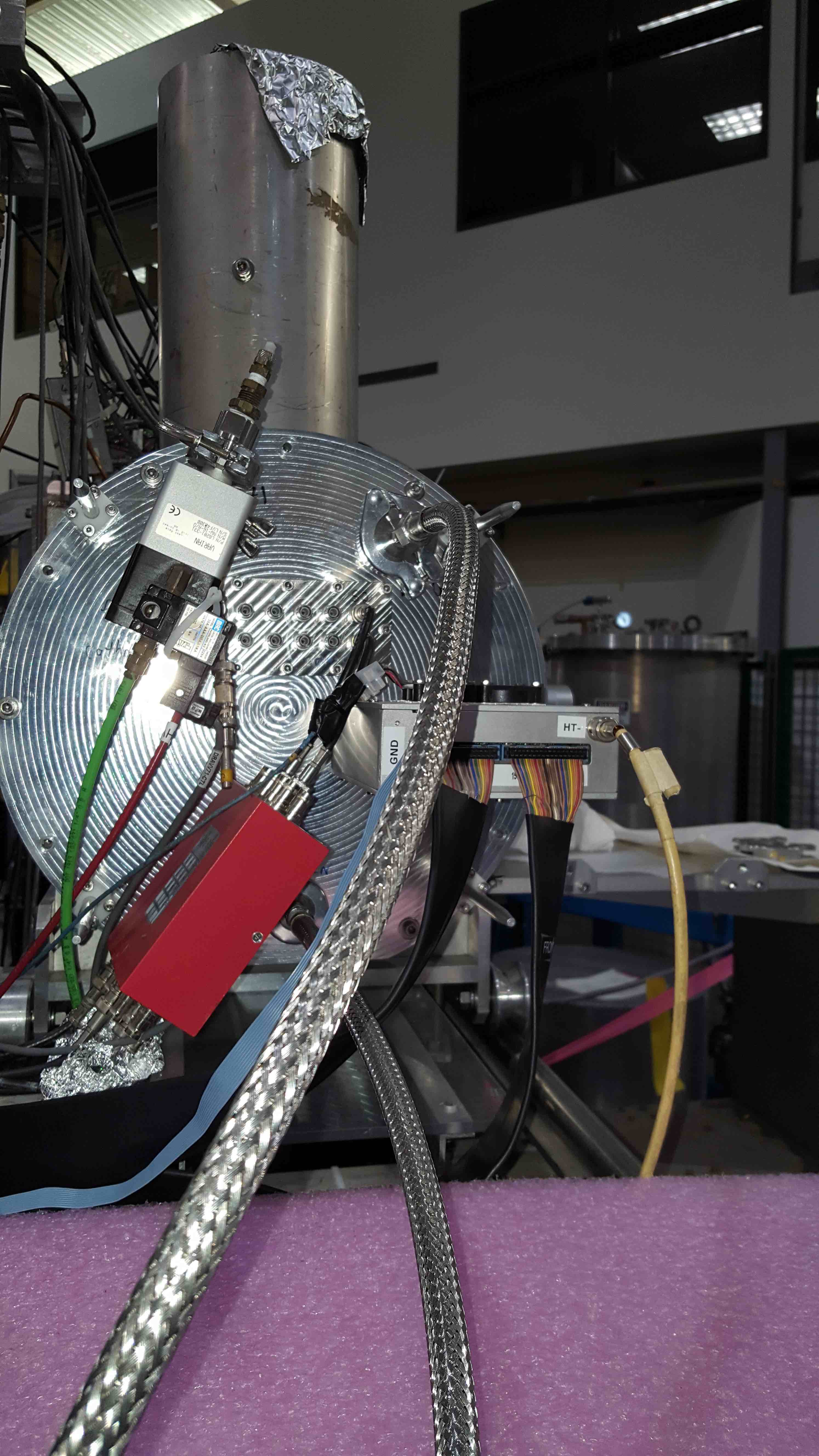
Attach IC electronics (compare Fig.5).
Electronics
The segmented IC anode is biased by CH1 of the MHV-4 mesytec power supply, providing +145V. Voltage is divided via a HV divider (custom) before going into two HV input channels (for the 2 anode segments) at the CAEN MOD A1422 hybrid charge sensitive preamplifier.
Anode output signals are preamplified via the same CAEN MOD unit (see Fig. 5 and 6). The A1422 is implemented into a red alloy box and features SHV connectors for the IN/DETECTOR and HV BIAS signals, LEMO connectors for the TEST IN and ENERGY OUT and a cable with a
D-type 9 pin male connector for the power supply. The output voltage is proportional to the amount of input charge.
Fig.5 - Hybrid IC electronics.
Fig.6 - Hybrid IC electronics.
The IC cathode is biased to -450 V via one of the negative polarity (max -5kV) orange Bertan PWS.
Anode signal ouputs from the preamplifier are fed into two individual ORTEC amplifiers (top rack at tail DAQ) before being processed.
The DSSSD is biased via the MHV-4 mesytec power supply, CH3 (-60V for presently installed DSSSD). Preamps and fans are biased via the multi channel +/-15V PWS. See DSSSD operation for more info on the electronics.
Connect all bias supplies and signal cables and check if crates are on.
Hybrid Operation
Follow the intructions to fill the IC with isobutane gas.
Slowly ramp up the IC bias for anode and cathode.
Turn on the DSSSD preamp PWS, and check if the fans are running.
Slowly start ramping up the DSSSD voltage. Ramp up in 2-5 V steps and record the leakage current for the DSSSD.
Normal V-I curves can be found in the DRAGON Hybrid Elog . Look them up before operating the hybrid for the first time, and be sure to know which DSSSD is installed.