div.container {
display:inline-block;
}
p {
text-align:center;
}
Removing/Installing a DSSSD
One should never touch the DSSSD or the fragile wires near the edges of the DSSSD.
This page outlines how to vent and pump down the DSSSD box, as well as how to mount/switch DSSSD detectors in the DSSSD box.
Should the DSSSD be installed in the hybrid detector, follow the instructions for hybrid detector operation instead.
To remove a DSSSD:
Turn down the bias voltage.
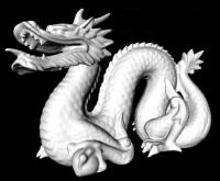
Presently we are using CH3 from a 4 channel mesytec power supply located in one of the tail racks (se Fig.1).
Fig.1 - Presently used DSSSD mesytec power supply.
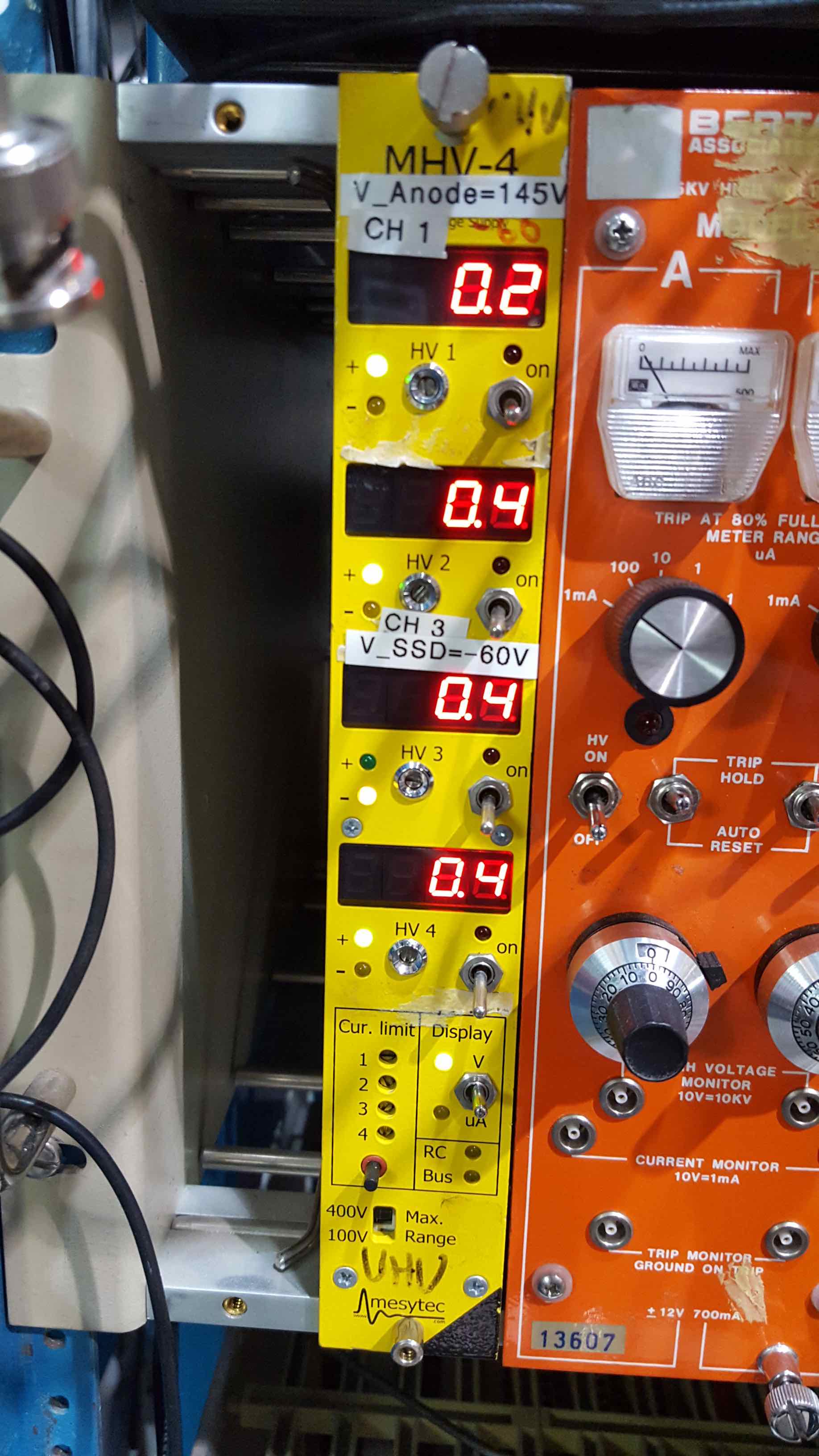
Turn off the preamp power supply, located at the bottom of the same tail rack (see Fig.2). It's the multi-channel +/-15 V PWS.
Fig.2 - Presently used DSSSD preamp power supply.
Vent the DSSSD box:
From EPICS page "ED2 to SSD", close IV61 and RV61 and RV63.
Make sure the TP61 ("Miniturbo") has been stopped and had time to spin down.
Waiting for 10min before venting should be sufficiently long for this particular turbo pump.
Though it's a small volume, vent with nitrogen if possible.
The nitrogen bottle is located next to MD2 on the S/E side of DRAGON. Just open the bottle, the needle valves should already be in the right position. Activate the "dead man" time switch.
Open vent valve VV61 and allow pressure to rise to atmospheric (Check DRA:CG61).
Close the nitrogen bottle.
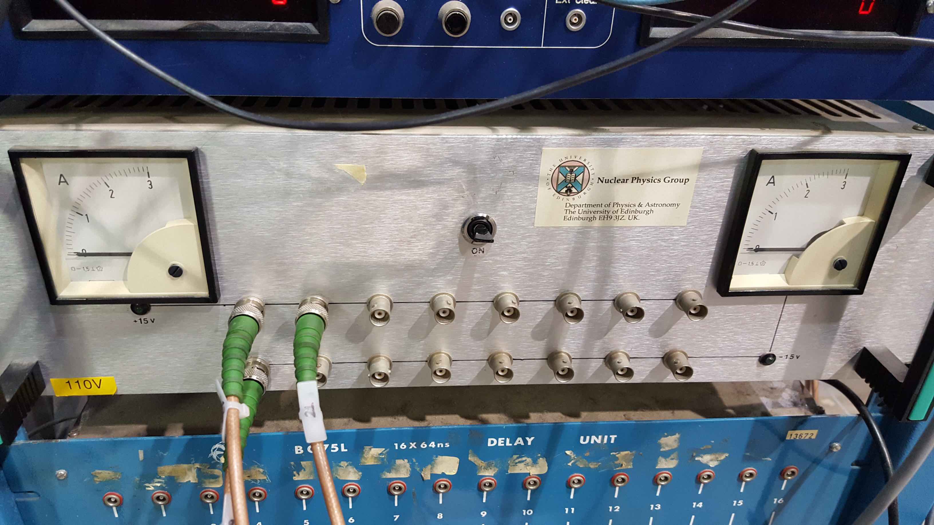
Remove the DSSSD preamp box:
Disconnect the HV PWS cable as well as the two ribbon cables at the back of the DSSSD preamp box (Fig.3).
Fig.3 - DSSSD preamp box.
Unscrew the lid of the box and place it somewhere close by (unless you disconnect the cables for the fan as well. Power for the fans is provided by the same +/-15V PWS as for the preamps.)
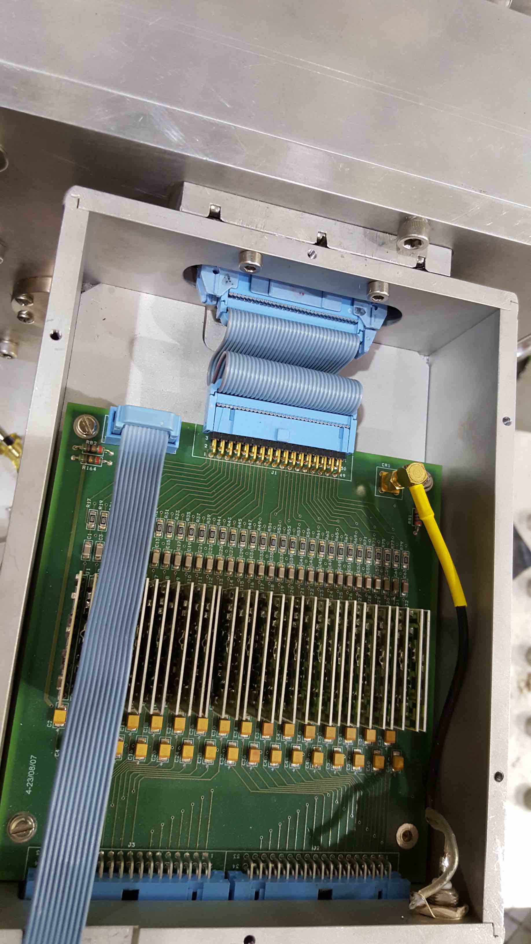
You will now see the preamp board (see Fig. 4). Disconnect the small blue ribbon cable that provides power for the preamps.
Fig.4 - DSSSD preamp board.
Now disconnect the 32 channel blue ribbon cable on the detector side.
Now disconnect the preamp box from the DSSSD box held by two head cap screws. You will need a 3mm hex for this.
Place the box somewhere safe.
Disconnect the DSSSD box from the FSB:
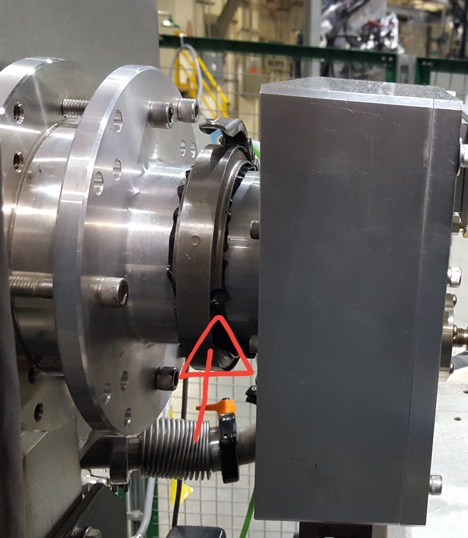
Ideally this is a two person job, since one person needs to hold the DSSSD box, while the other disconnects the TISOL clamp (see Fig. 5).
Fig.5 - DSSSD box connected to the FSB.
Take the box to a clean work surface, and remove the bolts.
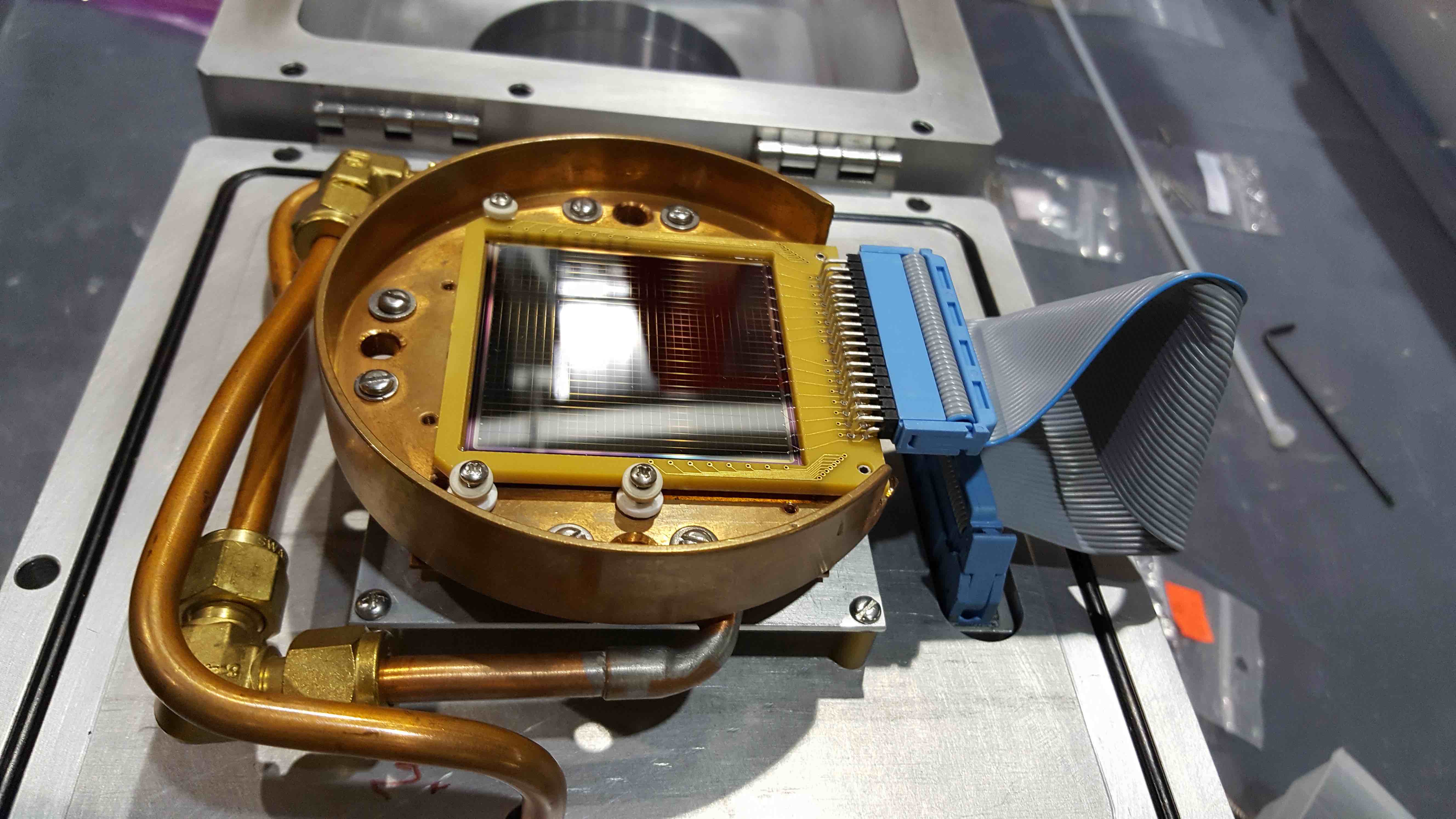
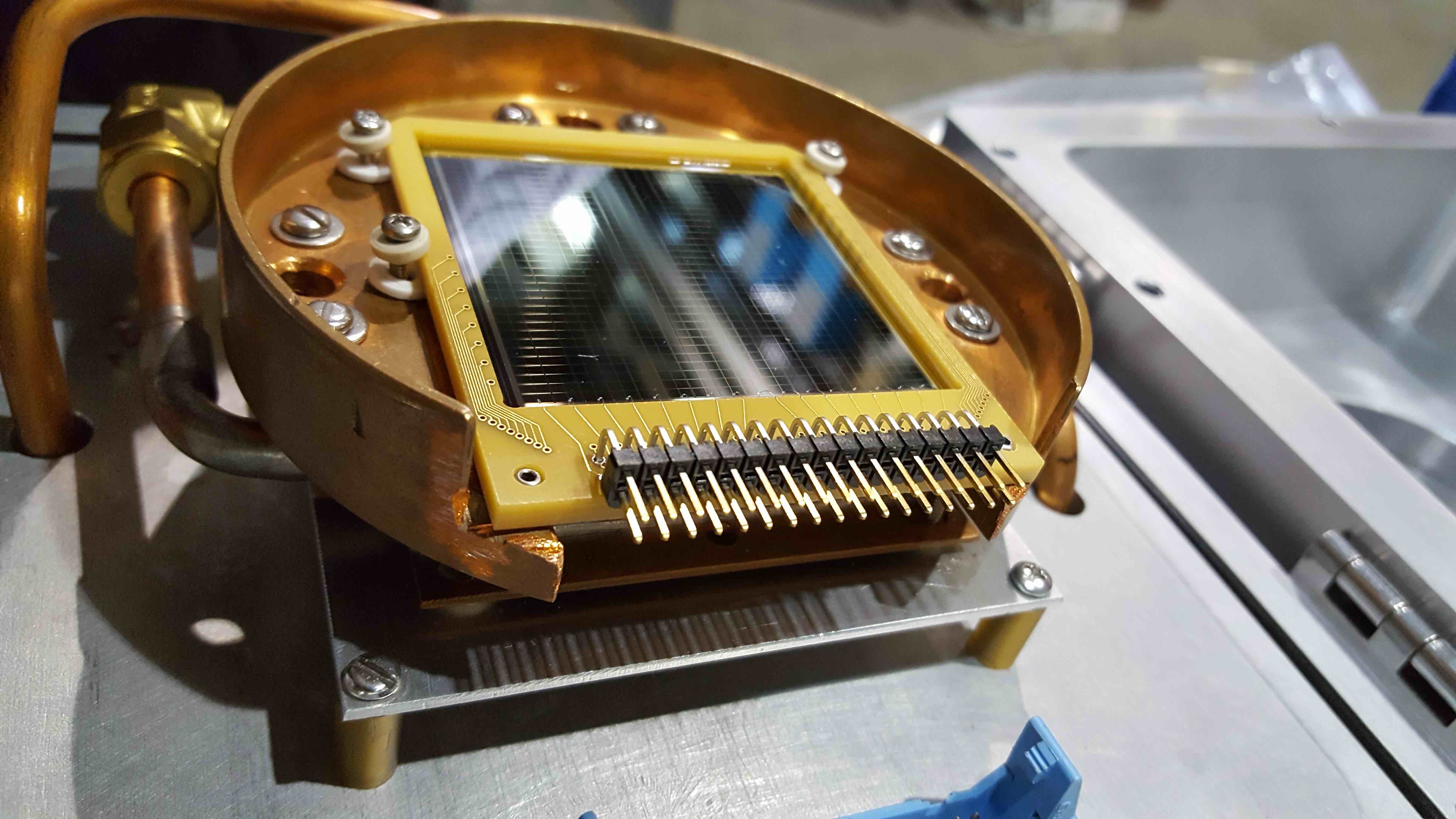
Rest the vacuum plate on a horizontal surface in a stable position with the cold plate facing upwards (see Fig. 6).
Fig.6 - DSSSD installed on cold plate.
Carefully disconnect the ribbon cable.
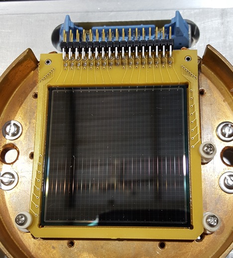
VERY CAREFULLY losen the set screws (seen in close up Fig. 7) with a small phillips head screw driver. You need steady hands and time to do this.
NEVER touch the DSSSD surface, or worse, scratch it with the tip of the screw driver! Same goes for the very fragile bond wires on the PCB board.
Fig.7 - DSSSD installed on cold plate.
Remove the DSSSD (only touch it on the edges of the boards), which is still held in place by two pins on either side of the connector.
To store the DSSSD place it in one of the designated storage boxes and store it with the others in the DRAGON cabinets.
To install a DSSSD:
Rest the vacuum plate on a horizontal surface in a stable position, with the cold plate facing upwards.
Clean the O-ring and relevant vacuum surfaces. Lightly grease the O-ring with vacuum grease and put it in place.
Remove the DSSSD from its storage box by touching only the edges of the G-10 DSSSD frame and take care to avoid touching the fragile bond wires at the edges of either active surface of the DSSSD or the surfaces themselves. If the wires are touched they will break, rendering certain strips useless. Wearing gloves will ensure that the DSSSD surface is not contaminated but gloves may hamper dexterity.
Place the DSSSD mounting holes over the two pins at the top of the cold plate and slowly lower the DSSSD onto the surface of the cold palte until it rests there. You should now see the strips as vertical, assuming that the pins are the top most edge (compare Fig.7).
Now secure the DSSSD with the small screws and ceramic spacers as shown in Fig. 6 and Fig.7. Again, be careful not to scratch the DSSSD or the bond wires. Do not attach screws on top of any bond wires.
Do not tighten the screws too much, since the board must not warp under to much pressure. This step requires lots of patience and steady hands
Fig.8 - DSSSD pin connector close up.
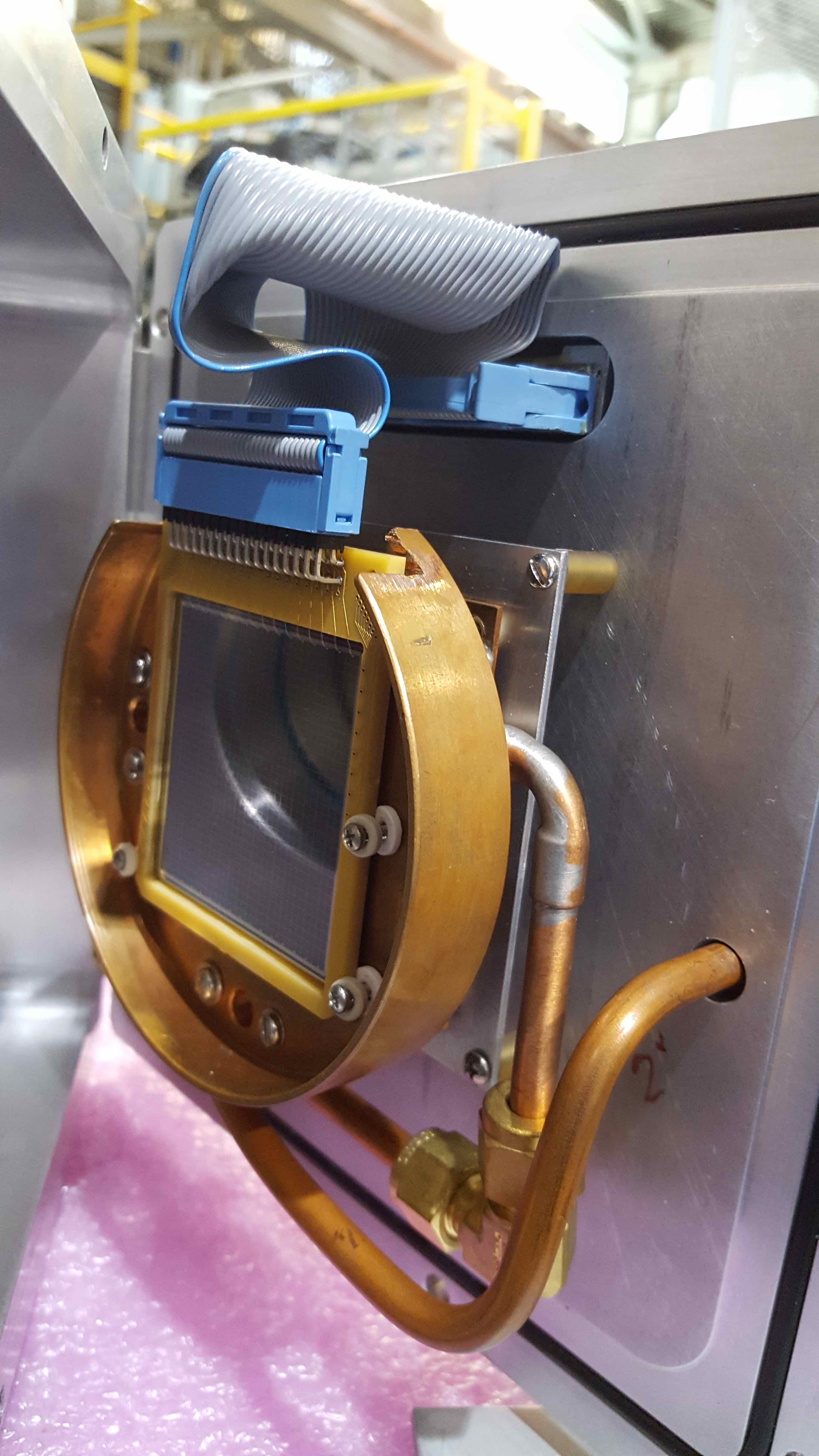
Connect the ribon cable to the pin headers at the top of the DSSSD. Pay attention to the orientation of the pin connector. In the pictures above, the connector was attached the wrong way around (Fig.8), forcing us to twist the ribbon cable accordingly (Fig.6)
Close up the DSSSD box and tighten the bolts. Mount the vacuum plate to the top of the TISOL box at the end of DRAGON, with the DSSSD facing the final slit box (shown in Fig. 9, but ideally box should be closed before attaching the DSSSD box to the FSB).
Fig.9 - DSSSD installed in DSSSD box facing FSB.
Attach the preamp box to the DSSSD box, and connect the ribbon cable from the preamplifier motherboard to the vacuum-feedthrough. Also connect the small ribbon cable to power the preamps (see Fig. 4).
Reattach the lid (including fans) of the box and tighten the screws. Be careful not to accidentaly squish the ribbon cable under the lid, but place it in the provided notch
Connect the HV bias cable.
Connect the ribbon cables to the preamp outputs for front an back strips at the back of the preamp box. Those go into the back of the RAL amplifiers via an inverter ribbon cable.
Pump the chamber down. The following method assumes the slit box is
pumped down and TP52 is on.
Do not bypass vacuum interlocks unless you are VERY certain it
is necessary. The interlocks are your protection against causing
inadvertent damage to pumps, detectors, gauges, foils, etc.
From EPICS page "ED2 to SSD", confirm that "SSD installed"
button on the lower left is green, indicating microswitch closure when the
DSSSD box is in position.
If that's not the case, check the position of the switch located at the end detector station, and select "DSSSD". If EPICS still doesn't recognize that the DSSSD is installed, make sure the "hidden switch" is activated.
To do so, push the movable platform under the DSSSD box all the way IN, and secure it with a small C-clamp if necessary to ensure it stays in it's position.
Turn on roughing pump RP21, open valve PV21 and wait until CG21A is below 0.1 Torr
Open roughing valves RV61 and RV63
When pressure at CG61 is below 0.16 Torr, close RV61 and RV63. Start BP31, open PV31 once pressure at CG31B is below 0.1Torr.
Open BV61 and start TP61.
There is no ion gauge installed to monitor pressure in the DSSSD box, so the only gauge is CG61 which is only sensitive within the mTorr to atm range.
If you have the time, pump on the box for a few hours to get the water vapour out before opening IV61 to connect to the FSB.
In any case, you need to be sure that the DSSSD box is sufficiently leak tight before opening IV61 to protect the sensitive MCP foils in the FSB.
Large pressure differentials could destroy them. Always move the MCP foils to the OUT position before opening IV61 or IV51.
Once IV61 is open and the pressure reading on IG52 is in the 10-6 Torr range, turn on the preamp power supply and also check if the fans are running.
Ramp up the bias voltage. In the absence of specific information for the installed detector, apply -50 V for 250 μm thick DSSSDs or -70 V for 300 μm thick DSSSDs slowly enough to avoid exceeding 1 μA
leakage current at any time (this should take ~ 30 sec.). Leakage current can be monitored with the present mesytec power supply, by turning the switch on the bottom right from "V" to "μA" (see Fig.1).